Measuring with capacitance sensors
Measuring with capacitance sensors
Capacitance sensors are noncontact sensors used in machine tools to measure the distance between a noncontact probe and a target sensor. Because the probe does not physically touch the target, capacitance sensors are beneficial in instances where the target surface is moving, such as a rotating spindle, or delicate, such as a silicon wafer.
Capacitance sensors are noncontact sensors used in machine tools to measure the distance between a noncontact probe and a target sensor. Because the probe does not physically touch the target, capacitance sensors are beneficial in instances where the target surface is moving, such as a rotating spindle, or delicate, such as a silicon wafer.
All images courtesy S. Smith
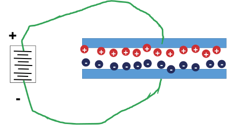
Figure 1. A flat-plate capacitor.
The operating principle is similar to that of a flat-plate capacitor. Figure 1 shows that when two conductive plates (blue) are connected to a voltage source (left) and separated by a nonconductive space (dielectric), positive charges collect on the top plate and negative charges on the bottom plate. A small current flows until the charge builds to its maximum value, and then no more current can flow. The amount of charge that builds up is related to the capacitance of the device, measured in farads.
If the voltage source is alternating rather than direct, the built-up charge reverses with the voltage, and some current is always flowing. With the plate area and the dielectric material fixed, a measurement of the current provides a measurement of the distance between the two plates. Larger plates that are closer together cause more current than smaller plates that are farther apart.
In machine tool sensor applications, one plate is the probe, and one plate is the target. The probe and the target are both connected to the voltage source and must be conductors.
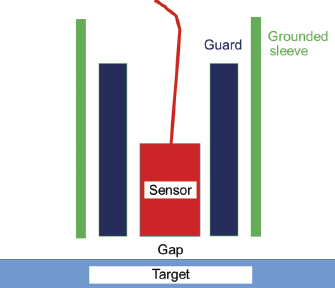
Figure 2. A capacitance sensor with a guard circuit.
The charge builds between the probe and any other nearby conductor, so an additional modification is made for a probe to measure capacitance in the direction it is pointed. First, the sensing element is surrounded by a guard element. Typically, this is a cylindrical sleeve that wraps around the sensor. The guard element is maintained at the same voltage as the sensing element, so there is no built-up charge between the sensor and the guard sleeve. Effectively, this "directs," or focuses, the capacitance sensing out the front of the probe toward the target. Next, the sensor is surrounded by and electrically insulated from a grounded sleeve. This allows the probe to be handled and mounted without impacting the measurement.
Capacitance sensors, or probes, can be used on any conducting target, meaning the measurement is the same, for example, for steel or aluminum targets. Therefore, unlike other noncontact probes, capacitance sensors are not sensitive to grain size or alloy variations. However, the dielectric constant of the gap (typically air) is affected by temperature, pressure and humidity. This means capacitance sensors must be protected from the environment because they do not work well in the presence of oil, coolant or water.
Capacitance probes are also sensitive to the shape of the sensor and target. The probes are typically flat on the end and are calibrated against a flat plate. If the target is curved, similar to the outer surface of a spindle, the output distance will differ from the calibrated distance, and calibration using the curved target can be required.
The measurement range is a function of the sensing area size. The greater the area, the larger the range. In general, the maximum gap at which a probe is useful is about 40 percent of the sensing area diameter. The resolution is typically about 1/10,000 of the full-scale range. A smaller probe with higher resolution must be mounted considerably closer to the target. The bandwidth, or the ability to measure a rapidly changing distance, depends on the frequency of the applied alternating voltage. As the frequency of the applied alternating voltage increases, the motion frequency the probe can detect also increases, along with the cost of the device.
Capacitance sensors have several purposes on machine tools, including spindle vibration, tool offset and runout measurement; tool, workpiece and fixture detection; short-range positioning feedback; and pressure measurement in combination with a flexible diaphragm. CTE

About the Author
Dr. Scott Smith is a professor and chair of the Department of Mechanical Engineering at the William States Lee College of Engineering, University of North Carolina at Charlotte, specializing in machine tool structural dynamics. Contact him via e-mail at [email protected].