Machine tools for cutting composite materials have unique requirements
The cover story for the December 2014 issue of Cutting Tool Engineering examines the unique requirements of machine tools used for cutting composite materials.
Although pricey, composite materials are strong, heat-resistant and lightweight and, therefore, continue to make inroads into a host of industries. Composite parts enable aircraft, for example, to reduce fuel consumption, improve combustor efficiency and power jet engines at a higher thrust. As a result, more composite parts will be machined for aircraft and other applications.
An array of materials fall under the composites umbrella, including fiberglass, ceramic matrix, carbon fiber reinforced and silicon carbide. Each type has unique characteristics, and differences exist even within the same type.
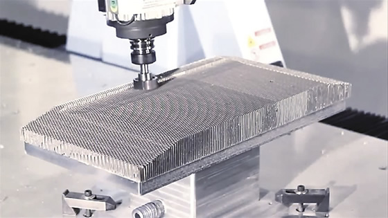
Courtesy of Diversified Machine Systems
Diversified Machine Systems cuts a honeycomb composite material on an enclosed 5-axis, large-format, overhead-gantry CNC router with continuous C-axis rotation.
“The number one thing in composite machining, which a lot of people don’t understand, is every program and every composite is different,” said Evan Kooda, senior manufacturing engineer for Janicki Industries Inc. “Every program has a different type of composite, and each requires different types of cutting tools.”
The Sedro-Woolley, Wash., company does lay up of composite parts, machines composites and builds machining centers for internal use. “Nobody else gets access to the technology we’ve developed in-house,” Kooda said.
The technology includes contra torque gear motors to eliminate backlash and allow a change in direction while machining without producing any slop in the machine, and linear motors on the X, Y and Z axes—similar to a maglev train. “There is no gearing in that system,” he added about the linear motors. “It’s just a motor against a magnet.”
Cutting Composites
Although cutting tools and machining techniques can vary for each composite workpiece, if a parts manufacturer has a top-of-the-line machine tool for the worst-case composite-machining scenarios, the machine can cut the full spectrum, according to Patrick Bollar, CEO of Diversified Machine Systems, Colorado Springs, Colo. The company builds machining centers for a wide customer base, with about 60 percent of the machines being one-offs that are shipped in 14 to 16 weeks, on average.
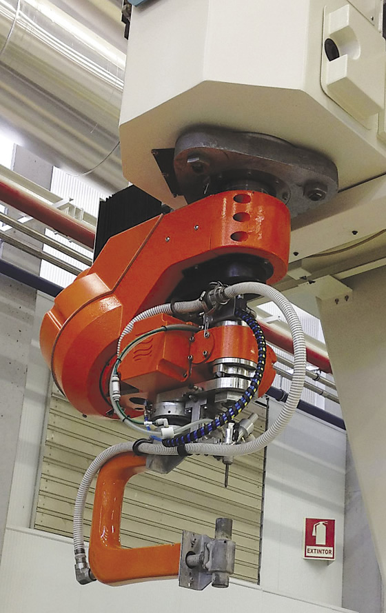
Courtesy of Flow Aerospace
In addition to a head for milling, drilling and routing, Flow Aerospace’s Composite Machining Center has a 5-axis waterjet head with an arm that functions as a 6th axis and holds a cup to catch the water, abrasive and material from the part.
He noted the DMS 3- and 5-axis machining centers provide a universal platform for machining aluminum, all forms of honeycomb material, composites, plastics, wood and foam.
A decade or so ago, Randy Von Moll, technical sales director for Fives Cincinnati, Hebron, Ky., said light-duty, accurate woodworking machines were frequently employed to produce composite aerospace parts that were not necessarily critical for safety, such as fairings and cover panels. However, with the current need to machine primary load-carrying airframe structures, those machines won’t cut it.
Airplane builders are becoming more like automakers, requiring that parts be manufactured to tighter tolerances so they bolt together without fitting operations during assembly. “This requires much more accurate and much more repeatable machine tools,” Von Moll said. “You need a machine that is very stiff.”
He added that the machine tool builder offers the Cincinnati Precision Mill and Trim (PMT) for machining cured composites, as well as nonferrous alloys. According to the company, the PMT performs 5-axis, five-sided maneuvering, is built on a rail-type, vertical-spindle gantry platform comprised of standard modules and offers an unlimited X-axis range and a traverse speed up to 60 m/min. (2,362 ipm).
Flow Aerospace LLC also offers a gantry-type machine for cutting composites, but with a twist. Chief Engineer Mark Saberton explained that its Composite Machining Center has two vertical masts on the gantry: One mast has a 5-axis drilling and routing head and the other has a 5-axis waterjet head with an arm that functions as a 6th axis and holds a cup to catch the water, abrasive and material from the part.
The captured material is evacuated through the machine and into a system that separates the water, which goes down the drain, from the solids, which are nonhazardous and deposited in a 55-gal. drum for disposal. The Jeffersonville, Ind., machine builder is part of the Ascent Integration & Automation Group of Ascent Aerospace, a wholly owned unit of AIP Aerospace, Santa Ana, Calif.
Down with Dust
Machining composites tends to generate a different type of chip than the metallic variety, one that resembles dust. Some people call them chips but they’re really tiny particles comprised of carbon and epoxy, Saberton said, adding that grain size varies along with the workpiece.
On the other hand, Tom Cornwell, sales and application specialist for LMT Onsrud LP, described the composite chips as microscopic “sixes” and “nines,” even if they appear to be a fine powder. The Waukegan, Ill., company makes cutting tools for machining advanced materials, such as the 66-700 series of diamond film-coated, low-helix tools for tackling abrasive composites.
“They will look like chips if everything is done right,” Cornwell said, noting that’s the case for the fibrous material and the resin, which holds the structure together. “It won’t be dust, it’ll be chips, and you can carry the heat away with the chips. That keeps the tool and the part cooler. The benefits are increased tool life and protection against the risk of part delamination.”
He added that the machining process is more like grinding than cutting, because of the smaller size of the chips.
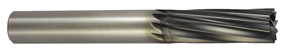
Courtesy of LMT Onsrud
LMT Onsrud offers cutting tools for machining carbon fiber-reinforced composites, such as the 66-700 series, with a low-helix flute angle to reduce vibration. According to the company, the open flute geometry dissipates heat to prevent resin flow.
Saberton concurred that the process is similar to grinding, where the tool fractures the workpiece, compared to the shearing action seen when machining metal. “Everybody tries to draw an analogy between machining metals and machining composites and there’s no correlation between the two whatsoever,” he emphasized. “If you try to shear a composite, you rip it to pieces.”
Nonetheless, metal can be found in composite structures, such as in sandwich-structured composites and other arrangements. “In a lot of cases, the outer skin of these aircraft will include some copper lightning-strike material, which also has to be machined as part of the process,” Cincinnati’s Von Moll said.
Whatever it’s called—microscopic chips, grains or dust—the material removed from the workpiece must be controlled and contained to prevent it from damaging machine components and electrical systems because it’s generally extremely abrasive and conductive. “If you get the dust, or chips, into electronic systems, they can literally short out the machine or cause a fire,” Von Moll said.
To protect sensitive electronics, such as the CNC, drive amplifiers and servos, the panels must be air conditioned and have positive air pressure to prevent drawing in the dusty debris, Von Moll explained.
Mechanical systems that can be negatively impacted by an abrasive material also must be protected. “We incorporate flexible covers over the way and bearing systems and also take secondary measures by applying positive pressure behind the covers to prevent dust from entering critical machine elements,” Von Moll said, adding that scales and feedback systems are also kept under positive pressure.
To limit abrasive composite dust from accessing critical components, Diversified Machine Systems developed an overhead gantry machine with a table that doesn’t move. Bollar explained that a conventional machine tool, where the tables moves left, right, forward and back, means the dust falls on a component that moves.
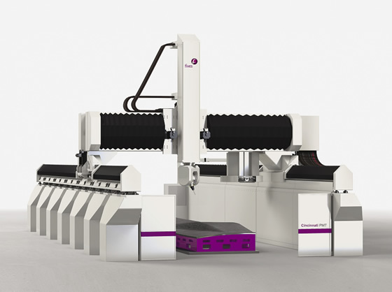
Courtesy of Fives Cincinnati
The Cincinnati Precision Mill and Trim (PMT) machine is built upon a rail-type, vertical-spindle gantry platform and provides 5-axis and five-sided maneuvering for machining large parts made of cured composites and nonferrous alloys.
Bollar added that electrical systems and critical components are fully protected, such as by putting Viton seals on and special pressurized bellows over the way system. In addition, the machine is enclosed to enable integration of a customer’s dust collection system and enhance worker safety. The company developed a dust hood to perform direct dust collection at the tool for 5-axis operations. However, end users sometimes must remove the hood to access space-restricted part features with a tool. “Our customers are leaning toward a full enclosure more than a dust hood because of its greater flexibility in tight spaces where dust hoods are not as practical,” Bollar said.
According to Bollar, it’s not unheard of for a commodity machine with a moving table to last only 6 days when machining abrasive composites, such as silicon carbide. “We’ve had our machines in this environment for almost 4 years and the machines are still working.”
Water World
Dust isn’t an issue when waterjetting composites on the Composite Machining Center, Saberton said. When milling and drilling, however, dust is a major problem, so the machine generates a cold air mist around the cutting tool to cool the tool and form a plume around it.
The dust gets caught in the plume before it has a chance to become airborne and falls down on the part, Saberton noted. The part is then hosed off, the dust goes into a pit underneath the machine and is processed through the filtering system that handles the waterjet waste. “There is no risk to the machine and no risk to people,” he said.
One approach Janicki Industries takes to control composite chips is enclosing the machine in a vacuum system to extract chips after using air at the spindle face to remove them from the cutting tool, Kooda noted. In addition to employing positive air pressure on all electrical boxes and critical components to keep dust out, all bearings are continually greased to prevent carbon fibers from infiltrating them.
Review the print ads from this magazine to continue
This quick advertiser review unlocks the rest of the article and keeps the full-screen reader focused on the ads instead of the page chrome.


MFGAxis Discussion