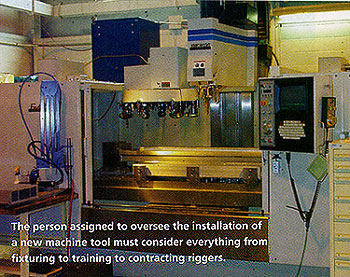
Overseeing the acquisition and setup of capital equipment is a lot of fun for most manufacturing engineers. It’s also a lot of pressure.
You’re put in charge of a project for which your company is laying out thousands, tens of thousands or even millions of dollars. Plus, management usually wants a quick return on its investment—sometimes within 90 days. Talk about being on the hot seat.
But where else would you rather be? A solid performance on a high-profile project can really boost your career.
Succeeding at these kinds of projects requires someone with the ability to handle the glare and heat of the spotlight. I discovered this a number of years ago, when my former employer assigned me the job of setting up a new machine tool. Mistakes were made, but I learned many things. I recount some of them in the following pages and offer advice that, I hope, will help make your next setup project a success.
Develop a Plan
The first order of business when assigned to bring a new machine tool online is to develop a plan. Start by asking a lot of questions. Which operators are going to run the new machine? How will they be trained? Who is going to program the new machine? What CAM package will be used? How will programs be sent back and forth? What types of cutting tools are needed? What holders? What fixtures? What about plumbing for the machine? Air? Does it need a foundation? Where is it going to be situated in the shop? What equipment has to be moved to accommodate the machine? Where is the stock going to reside? What about material handling?
All of these questions need to be addressed to ensure that everything runs smoothly when the new machine hits the floor. And if possible, get involved early in the planning process.
When I was appointed to head up the project at my old company, management had already approved the plan to acquire the new machine—a CNC vertical milling center. Management’s failure to include me in the project from the beginning was a mistake. I didn’t know what parts were to be run or what ROI was expected. My supervisor simply handed me a stack of handwritten notes, blueprints and product literature describing the machine and told me that it would be delivered in 90 days. The clock was ticking before I even got out of the gate.
My immediate goals were to understand the new milling machine’s capabilities and determine whether or not it could accommodate the parts assigned to run on it. At the time, a horizontal boring mill was producing the parts, a family of 24 aluminum extrusions. The extrusion with the longest lead time took more than two days to complete. It was 48.000" long, 4.875" high, 13.875" wide and had 0.750"-thick walls. I determined that the new machine would be able to produce all of the parts.
Order Tools, Fixtures Immediately
Next, I turned my attention to tooling. Tools need to be ordered right away. Some tools will be specials, of course, which makes the timing just that much more critical. You should know what type of spindle your machine has, so you know what type of tooling to order.
Examine the blueprints of the parts that the machine will be producing to determine what tools you will need. For organizational purposes, I recorded the following on a spreadsheet: the parts to be produced, the tools needed to machine them and which tools could machine multiple parts. I used this information to pare down to a minimum the number of tools that would be required to machine the 24 extrusions.
One of the more interesting challenges of my project was machining the ends of the extrusions without refixturing them. I determined that the only way to accomplish this was to use right-angle heads. Most of them, though, were too heavy for the tool turret to support (Figure 1). The turret could hold tools that weighed 14.7 lbs. or less. I eventually located 13.2-lb. heads that fit into the CNC turret.
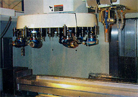
Figure 1: To reduce setup times, right-angle heads were loaded into the turret. Finding heads that were light enough to allow this proved challenging.
These were easily the most expensive items in my tooling budget. I bought eight heads, even though I only needed six. The two extra heads allowed dull or broken tools to be changed out quickly, and, more importantly, they permitted us to put in place a “swap-out” maintenance program. The operator could replace one head, send it out to be refurbished and have it returned before the replacement head was scheduled for maintenance. This program helped eliminate downtime and unexpected tool failures.
If your tool budget allows, order three of every type of tool. Having spares on hand during the machine prove-out stage could save you enormous headaches.
Unless your shop is making the often-mentioned but seldom-seen “widget,” the item with the longest lead time will be the new machine’s fixtures. Obtaining them could also prove to be your biggest challenge.
The parts in my project needed to be machined on all six sides. I had to come up with a design for fixturing that would automatically present all sides of the part to the spindle. The fixturing on the old horizontal boring mill was no help. The 48"-long extrusion mentioned earlier had been held on the table with top clamps and toe clamps. Machining it involved six different setups, which helps explain why it took two days to machine.
My fixturing solution came during a brainstorming session with some of my colleagues. We first discussed suspending the part on a sort of bullnose center between two rotary tables. But we concluded that the middle of the part wouldn’t be supported properly. Then we thought of running some sort of support through the extrusion, but that would make changing parts too difficult. Next, we came up with the idea of using a suspended table between the rotary tables, but we decided that it wouldn’t allow the machining of the side of the part that sits on the table.
We finally concluded that the machine envelope could accommodate a stationary fixture toward the front and a rotary fixture toward the back. Fixturing based on this idea was developed (Figure 2). With some changing out of locators, it would accommodate all of the parts.
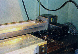
Figure 2: Fixturing was a big challenge. All six sides of the parts had to be automatically presented to the spindle. A system was designed that incorporated a stationary fixture at the front of the bed and a rotary fixture at the back.
The design was sent to a local tool-and-die shop. Because of various revisions to the design and the shop’s backlog, the fixturing would take six weeks to complete. Six weeks! I had only three weeks for installation and testing before production was expected.
Waiting too long to design the fixturing was the biggest mistake made during the project. Unless you plan to use vises, fixturing will probably be the item with the longest lead time. Get going on it early.
More advice on fixtures: Specify the beefiest ones you can. If fixtures made of 1"-thick material will do, go with material 2" thick. I’ve never seen a fixture that was “too stiff,” but I’ve seen plenty that were not stiff enough.
Programming and Training
You will probably have to rework your existing part programs before the new machine hits the floor. Do this as soon as you can.
Fortunately, my company already had a solid CAM package in place. We also had one of the best programmers that I’ve ever met. Before the new vertical milling center was in-house, he and I developed programs for six of the 24 parts it would eventually produce. Not everything that we tried worked out, but at least I had a handful of good, solid CAM programs that I knew would not crash and could be tweaked on the machine.
Think about training the personnel who will operate new equipment. As soon as I was named project leader, I arranged for myself and our operators, programmers and maintenance personnel to attend training sessions. This provided a couple of benefits.
One was that it calmed certain fears that had been brewing among shop-floor personnel about the machine’s enhanced capabilities. Some worried because its spindle rotated twice as fast as any other CNC equipment we had, it permitted the feed to be more than tripled and it featured nearly double the rapid-traverse rates. During the training sessions, personnel gained confidence that they could handle the machine. The sessions also helped prepare the maintenance people to diagnose problems after the machine’s one-year warranty was up.
Another detail that needs to be taken care of before the scheduled startup is preparation of the site where the machine tool will sit. The machine builder will tell you exactly what you will need. My company’s maintenance man was glad to take over this part of the project, and he did an outstanding job. The site had air, water and power ready to go two weeks before the scheduled delivery date. Maintenance personnel are key players on your team, so bring them into the process early.
The Big Day
Two weeks before the machine was delivered, I sat down to figure out exactly where we stood. The tools were in. I had six solid programs that would allow me to begin machining parts two days after delivery and that provided an excellent framework for the rest of the parts. Operator training was complete. The site was prepped. The only item not on schedule was the fixturing, and it wasn’t going to be done on time.
Hounding the tool-and-die shop we had contracted to build the fixtures wouldn’t do any good, so I activated Plan B. (Always have a Plan B—and Plans C, D and E.) My Plan B was to use the top clamps and toe clamps from the old horizontal boring mill to hold the prove-out part. Doing so would allow management to at least see chips made right away.
At 7:45 p.m. on the day of the scheduled delivery, I got “the call.” The machine was on the dock. I immediately drove to the shop. When I got there, the riggers—who also have to be contracted—were just lifting the machine off of a flatbed truck and onto the dock. That night, we got the equipment to its location and went home.
When I came back the next morning, the entire shop was abuzz about the arrival of the new machine. My boss pulled me into his office. His only words were, “Two days.” The pressure was on.
The machine builder’s serviceman was already on the shop floor, setting up the machine. He told me that I could start loading tools and programs by 10 a.m. Maintenance got all the hookups done; everything fit perfectly. I started loading tools at 10, as promised.
Then I encountered the first glitch. I had lined up the right-angle heads in sequential tool spots. This was a mistake. The tools were so heavy on one side of the turret that they were not allowing it to index.
This may seem like a minor problem, but I was in a panic. I had to rearrange the entire turret. All of the programs had to be changed to reflect the changes in tool numbers. The T6 slot, for example, was no longer a left-facing 1 1/4" endmill for milling part ends. Now it was a 1/4-20 tap. Thank goodness for CAM. My programmer was able to complete the changes and get me all new programs in just a couple of hours. None of the tool paths changed, just the tool numbers.
By the time my programmer gave me the new programs, I had rearranged the tools and the serviceman had started the 24-hour runoff. Once the runoff was completed, I would have 18 hours left to prepare the new machine to enter production. The serviceman assured me that I could upload programs while the machine ran in the background.
The stationary fixturing was ready to set up, the tooling was ready, the programs were ready and everything that could be prepared in advance was set for the first day of production.
The happy ending to this story is that I got the machine up and running on time and on budget—a result of planning, teamwork and having a backup plan.
My advice to any engineer overseeing the acquisition of new equipment is to make a plan and stick to it. And don’t listen to the naysayers. I had more people tell me that things wouldn’t work during this project than ever before in my career.
If there is solid engineering behind what you’re trying to do, go for it. If your plan fails, you’ll have learned something. If it proves successful, you’ll also have learned something—and maybe given your career a major boost.
About the Author
Michael Gugger is a project engineer and tooling specialist at the Institute of Advanced Manufacturing Sciences, Cincinnati.
Related Glossary Terms
- boring
boring
Enlarging a hole that already has been drilled or cored. Generally, it is an operation of truing the previously drilled hole with a single-point, lathe-type tool. Boring is essentially internal turning, in that usually a single-point cutting tool forms the internal shape. Some tools are available with two cutting edges to balance cutting forces.
- computer numerical control ( CNC)
computer numerical control ( CNC)
Microprocessor-based controller dedicated to a machine tool that permits the creation or modification of parts. Programmed numerical control activates the machine’s servos and spindle drives and controls the various machining operations. See DNC, direct numerical control; NC, numerical control.
- computer-aided manufacturing ( CAM)
computer-aided manufacturing ( CAM)
Use of computers to control machining and manufacturing processes.
- endmill
endmill
Milling cutter held by its shank that cuts on its periphery and, if so configured, on its free end. Takes a variety of shapes (single- and double-end, roughing, ballnose and cup-end) and sizes (stub, medium, long and extra-long). Also comes with differing numbers of flutes.
- extrusion
extrusion
Conversion of an ingot or billet into lengths of uniform cross section by forcing metal to flow plastically through a die orifice.
- feed
feed
Rate of change of position of the tool as a whole, relative to the workpiece while cutting.
- fixture
fixture
Device, often made in-house, that holds a specific workpiece. See jig; modular fixturing.
- gang cutting ( milling)
gang cutting ( milling)
Machining with several cutters mounted on a single arbor, generally for simultaneous cutting.
- milling
milling
Machining operation in which metal or other material is removed by applying power to a rotating cutter. In vertical milling, the cutting tool is mounted vertically on the spindle. In horizontal milling, the cutting tool is mounted horizontally, either directly on the spindle or on an arbor. Horizontal milling is further broken down into conventional milling, where the cutter rotates opposite the direction of feed, or “up” into the workpiece; and climb milling, where the cutter rotates in the direction of feed, or “down” into the workpiece. Milling operations include plane or surface milling, endmilling, facemilling, angle milling, form milling and profiling.
- milling machine ( mill)
milling machine ( mill)
Runs endmills and arbor-mounted milling cutters. Features include a head with a spindle that drives the cutters; a column, knee and table that provide motion in the three Cartesian axes; and a base that supports the components and houses the cutting-fluid pump and reservoir. The work is mounted on the table and fed into the rotating cutter or endmill to accomplish the milling steps; vertical milling machines also feed endmills into the work by means of a spindle-mounted quill. Models range from small manual machines to big bed-type and duplex mills. All take one of three basic forms: vertical, horizontal or convertible horizontal/vertical. Vertical machines may be knee-type (the table is mounted on a knee that can be elevated) or bed-type (the table is securely supported and only moves horizontally). In general, horizontal machines are bigger and more powerful, while vertical machines are lighter but more versatile and easier to set up and operate.
- tap
tap
Cylindrical tool that cuts internal threads and has flutes to remove chips and carry tapping fluid to the point of cut. Normally used on a drill press or tapping machine but also may be operated manually. See tapping.