Solid carbide is edging out HSS as the optimal tool material for holemaking and hole-finishing operations.
It’s easy to understand why drill/reamers have become so popular. By combining drilling and reaming into a single operation, these tools shave precious seconds off machining time in holemaking and hole-finishing applications, while providing the additional benefit of low tool costs.
Drill/reamers have traditionally been designed as double-margin, step-diameter, HSS tools. However, process changes in the manufacture of advanced submicrograin carbides have led to the development of single-margin, single-diameter, solid-carbide drills that can produce reamer-quality finishes. This high performance wasn’t possible with older carbide drills, which lacked the wear resistance and toughness provided by the tight grain structure of submicrograin carbides. Because these new grades provide greater resistance to heat, temperature shock, and wear than previous grades, carbide tool materials can now be applied in areas that were previously untouchable.
Drill users may balk at the relatively high purchase price of solid-carbide drills until they consider carbide’s advantages in terms of speed, feed, accuracy, hole finish, and number of regrinds. Solid-carbide drills are generally more expensive than HSS drill/reamers, but they can last from three to 10 times longer, depending on the application and machine setup. This longer tool life, coupled with carbide’s ability to drastically reduce cycle time, makes carbide an economical choice for making and finishing holes up to 20mm in diameter.
In the past, when machines lacked the necessary horsepower, speeds, feeds, and rigidity to handle the relatively brittle carbide, HSS was the most cost-effective material for hole-finishing tools. However, when used on today’s more advanced equipment, carbide tools are less likely to chip or break. With fewer premature tool failures, the cost of solid-carbide tools figured on a per-part-machined basis is no longer prohibitive. Through the application of advanced carbide grades, tool designs, and coatings, tool manufacturers have developed solid-carbide drills that can make and finish holes in one pass. Users of these tools can cut cycle time and boost the efficiency of expensive machine tools, flexible manufacturing systems, and transfer machines. Because modern solid-carbide drills allow holemaking and hole-finishing operations to be completed with fewer tools and in less time, they are considered more cost-effective than HSS drill/reamers.
Shorter cycle time and longer tool life aren’t the only factors that minimize manufacturing costs, however. In addition to improving efficiency by combining the operations of spot drilling, drilling, coring, and reaming, solid-carbide drills reduce the number of scrapped parts due to poor-quality holes. These tools can meet or exceed exacting requirements for hole size, finish, position, straightness, and roundness.

With three flutes, this solid-carbide drill can produce high-quality holes that do not require additional finishing operations.
Hole Quality
The superior strength and rigidity of carbide is one of the main reasons why solid-carbide drills offer better positional and dimensional accuracy than do HSS hole-finishing tools. Three factors that decisively influence hole quality are positional tolerance, alignment accuracy, and concentricity.
Positional tolerance is the amount by which the hole deviates from the true center. Solid-carbide drills can provide 75% to 80% better positional accuracy than HSS drill/reamers can.
Alignment accuracy (straightness) is the amount the hole wall, as a cylinder, deviates from strict alignment with the nominal axis. Compared to HSS drill/reamers, solid-carbide drills can improve alignment accuracy by as much as 90% with variances as small as 16.6µm (Figure 1).
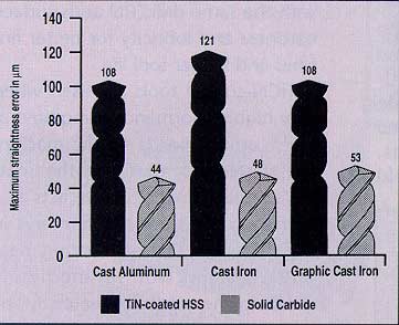
Figure 1:As this comparison chart shows, holes produced by solid-carbide drills are considerably straighter than those produced by TiN-coated HSS drills.
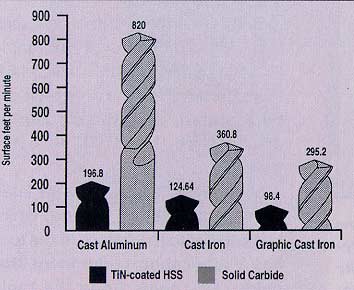
Figure 2:In tests, users were able to drill holes with solid-carbide drills at surface speeds that were faster than the speeds they could use with TiN-coated HSS drills.
Because solid-carbide drills do not bend and walk the way HSS drill/reamers tend to do, the concentricity (roundness) of the hole can be improved as much as 98%. When applied properly, solid-carbide drills can produce reamer-class hole finishes drilling from solid.
Two reasons why modern solid-carbide drills produce high-quality surface finishes are the improved rigidity and wear resistance of new carbide grades. The improved rigidity prevents radial twist and torsional vibration of the tool, thereby reducing chatter on the surface of the hole wall. The improved wear resistance increases tool life, holding finishes for more parts. Under optimal conditions, surface finishes measured by peak-to-valley height can improve as much as 80% over those produced by HSS drill/reamers.
A third reason solid-carbide drills offer better surface quality is that they can be run at faster cutting rates (Figure 2). Increasing the cutting speed reduces built-up edge on the tool, which can scratch and abrade the surface of the workpiece. By reducing cutting time, the higher cutting speed generates less heat on the workpiece surface. There is also less wear on the lands and outer corners of the tool, which directly influences the surface quality. At faster cutting rates, the tool "bites" the material better, cuts cleaner, and produces a better surface finish.
Drill Design
Improvements in solid-carbide drill designs offer an even greater potential for optimizing hole quality. New point grinds have been developed to handle higher speeds and feed rates while providing trouble-free chip removal. Self-centering points on solid-carbide drills eliminate the need for spot drilling. The tip starts to cut as soon as it makes contact with the workpiece, which prevents the tool from wandering.
Solid-carbide drills with three flutes remove more metal per revolution than 2-flute HSS drill/ reamers, while their open-flute design efficiently carries away chips. Even though the size of a single flute is smaller than a single flute on a 2-flute drill, the addition of the third flute increases total flute spacing over that of the 2-flute tool. The third cutting edge enables the drill to track straighter while in the hole, which vastly reduces runout. The additional margin supports the tool in the hole, producing reamer-class surface finishes. The 3-flute design also allows the tool to start or end on uneven surfaces and to handle interrupted cuts without deflection.
When excessive heat and chips interfere with drilling, solid-carbide tools with through-coolant capabilities may be used to heat buildup at the cutting interface and facilitate chip evacuation. A new drill design has internal coolant ducts following the helix angle of the flutes instead of going down the center of the web (Figure 3). Helical coolat ducts increase coolant volume through the tool, provide greater web strength and rigidity, and allow for more regrinds. Theoretically, solid-carbide drills with helical coolant holes can be resharpened down the entire length of the flute, and the coolant holes will not change position.
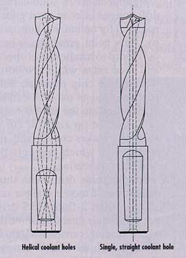
Figure 3:Helical coolant holes allow the drill on the left to be sharpened repeatedly. A drill like the tool on the right, with a single coolant hole running the length of its web and splitting only the end, can be resharpened only until the central coolant hole becomes exposed.
Solid-carbide drills typically range in size from 3mm to 20mm in diameter without coolant holes and from 5mm to 20mm in diameter with coolant holes. They are capable of drilling depths up to 7 diameters, both horizontally and vertically. When used in rigid, well-maintained machines, solid-carbide drills operate with high precision and withstand high loading conditions. These single-diameter tools can hold tolerances as tight as those produced by HSS drill/reamers or by drilling and reaming separately.
However, the ability to produce reamer-like hole sizes and finishes in one pass can be destroyed by runout error. Solid-carbide drill users can minimize runout by selecting a reliable toolholding system.
Toolholder Design
Spindle concentricity errors place heavy loads on a solid-carbide drill. Runout error will force the tool off-center. If the drill has a self-centering point, this will cause rubbing and premature tool wear as the drill tries to pull itself back to the center. Therefore, the greater the concentricity error, the shorter the tool life.
The total concentricity error measured at the cutting edges of the drill is the sum of the individual errors of machine spindle, machine interface, toolholder, and cutting tool. In modern practice, the toolholder contributes most to concentricity error.
As a general recommendation, the total concentricity error measured as TIR at the cutting edges of a solid-carbide drill should be less than 0.02mm (with the tool clamped in the machine spindle). If runout exceeds 0.02mm, it can reduce tool life 75% to 80%. When using solid-carbide drills in well-maintained machines, the concentricity error will not normally exceed 0.01mm TIR.
Almost any type of toolholder is suitable for holding a solid-carbide drill, but HSK toolholding systems offer the best accuracy. When used with precision hole-finishing tools, modular HSK holders handle the need for accurate location and tight positional tolerances.
With their hollow-shank taper design, HSK toolholders offer high static and dynamic rigidity but weigh 50% less than conventional ISO holders. They also have high torque transmission and defined radial positioning through full face and taper contact. Tool-change accuracy and repeatability are within 0.002mm. HSK holders offer short tool-change times and are available in automatic and manual tool-change modes. They have through-coolant capabilities and perform well on high-speed machines.
Coatings for Solid-Carbide Drills
The quality of solid-carbide drills depends to a great extent on whether tool manufacturers can produce their own carbide and coat their own tools, or whether this work is sent out to a subcontractor. The complicated procedures involved in the preparation and batching of tools for coating require the services of a specially trained work force.
Currently, most solid-carbide drills are coated with titanium nitride (TiN), titanium carbonitride (TiCN), and titanium aluminum nitride (TiAlN). The majority have the cost-effective TiN coating. TiCN, TiAlN, and new coatings based on molybdenum disulfide (MoS2) are playing a larger role in special applications such as dry and high-speed machining.
TiN is a general-purpose coating that is suitable for machining different materials in the same operation with the same drill. TiN adds surface hardness and lubricity for better finishes and longer tool life.
TiCN-coated tools are used when very high performance is required at high cutting speeds. In the machining of steel, for example, the coating’s multilayered structure acts as a barrier to the spread of fractures in the coating, thus preventing heat and abrasion from immediately reaching the substrate material. The advantages of TiCN-coated tools are weakened after regrinding, however, since the recoating process can’t recreate the multilayered TiCN coating. Reground tools can only be recoated with TiN.
TiAIN is considered the best solution to the problems of machining abrasive materials with solid-carbide tools. Because TiAIN-coated tools can be recoated, their benefit can be greater than that of TiCN-coated tools.
MoS2-based coatings are the latest technology. The soft coating, which is injected into the surface of the tool, has a lubricating component that helps carry chips along the tool’s flutes and away from the hole. By reducing chip buildup, this coating improves tool life and hole finish.
About the Author
Timothy White is plant manager for Guhring Inc., Brookfield, WI.
Related Glossary Terms
- abrasive
abrasive
Substance used for grinding, honing, lapping, superfinishing and polishing. Examples include garnet, emery, corundum, silicon carbide, cubic boron nitride and diamond in various grit sizes.
- built-up edge ( BUE)
built-up edge ( BUE)
1. Permanently damaging a metal by heating to cause either incipient melting or intergranular oxidation. 2. In grinding, getting the workpiece hot enough to cause discoloration or to change the microstructure by tempering or hardening.
- chatter
chatter
Condition of vibration involving the machine, workpiece and cutting tool. Once this condition arises, it is often self-sustaining until the problem is corrected. Chatter can be identified when lines or grooves appear at regular intervals in the workpiece. These lines or grooves are caused by the teeth of the cutter as they vibrate in and out of the workpiece and their spacing depends on the frequency of vibration.
- coolant
coolant
Fluid that reduces temperature buildup at the tool/workpiece interface during machining. Normally takes the form of a liquid such as soluble or chemical mixtures (semisynthetic, synthetic) but can be pressurized air or other gas. Because of water’s ability to absorb great quantities of heat, it is widely used as a coolant and vehicle for various cutting compounds, with the water-to-compound ratio varying with the machining task. See cutting fluid; semisynthetic cutting fluid; soluble-oil cutting fluid; synthetic cutting fluid.
- cutting speed
cutting speed
Tangential velocity on the surface of the tool or workpiece at the cutting interface. The formula for cutting speed (sfm) is tool diameter 5 0.26 5 spindle speed (rpm). The formula for feed per tooth (fpt) is table feed (ipm)/number of flutes/spindle speed (rpm). The formula for spindle speed (rpm) is cutting speed (sfm) 5 3.82/tool diameter. The formula for table feed (ipm) is feed per tooth (ftp) 5 number of tool flutes 5 spindle speed (rpm).
- feed
feed
Rate of change of position of the tool as a whole, relative to the workpiece while cutting.
- flutes
flutes
Grooves and spaces in the body of a tool that permit chip removal from, and cutting-fluid application to, the point of cut.
- hardness
hardness
Hardness is a measure of the resistance of a material to surface indentation or abrasion. There is no absolute scale for hardness. In order to express hardness quantitatively, each type of test has its own scale, which defines hardness. Indentation hardness obtained through static methods is measured by Brinell, Rockwell, Vickers and Knoop tests. Hardness without indentation is measured by a dynamic method, known as the Scleroscope test.
- helix angle
helix angle
Angle that the tool’s leading edge makes with the plane of its centerline.
- high-speed steels ( HSS)
high-speed steels ( HSS)
Available in two major types: tungsten high-speed steels (designated by letter T having tungsten as the principal alloying element) and molybdenum high-speed steels (designated by letter M having molybdenum as the principal alloying element). The type T high-speed steels containing cobalt have higher wear resistance and greater red (hot) hardness, withstanding cutting temperature up to 1,100º F (590º C). The type T steels are used to fabricate metalcutting tools (milling cutters, drills, reamers and taps), woodworking tools, various types of punches and dies, ball and roller bearings. The type M steels are used for cutting tools and various types of dies.
- lubricity
lubricity
Measure of the relative efficiency with which a cutting fluid or lubricant reduces friction between surfaces.
- titanium aluminum nitride ( TiAlN)
titanium aluminum nitride ( TiAlN)
Often used as a tool coating. AlTiN indicates the aluminum content is greater than the titanium. See coated tools.
- titanium aluminum nitride ( TiAlN)2
titanium aluminum nitride ( TiAlN)
Often used as a tool coating. AlTiN indicates the aluminum content is greater than the titanium. See coated tools.
- titanium carbonitride ( TiCN)
titanium carbonitride ( TiCN)
Often used as a tool coating. See coated tools.
- titanium carbonitride ( TiCN)2
titanium carbonitride ( TiCN)
Often used as a tool coating. See coated tools.
- titanium nitride ( TiN)
titanium nitride ( TiN)
Added to titanium-carbide tooling to permit machining of hard metals at high speeds. Also used as a tool coating. See coated tools.
- titanium nitride ( TiN)2
titanium nitride ( TiN)
Added to titanium-carbide tooling to permit machining of hard metals at high speeds. Also used as a tool coating. See coated tools.
- tolerance
tolerance
Minimum and maximum amount a workpiece dimension is allowed to vary from a set standard and still be acceptable.
- toolholder
toolholder
Secures a cutting tool during a machining operation. Basic types include block, cartridge, chuck, collet, fixed, modular, quick-change and rotating.
- total indicator runout ( TIR)
total indicator runout ( TIR)
Combined variations of all dimensions of a workpiece, measured with an indicator, determined by rotating the part 360°.
- wear resistance
wear resistance
Ability of the tool to withstand stresses that cause it to wear during cutting; an attribute linked to alloy composition, base material, thermal conditions, type of tooling and operation and other variables.
- web
web
On a rotating tool, the portion of the tool body that joins the lands. Web is thicker at the shank end, relative to the point end, providing maximum torsional strength.