An end user discovers how quickly the best-laid plans can go awry when hard turning powder metal.
After reading the print specifications, a manufacturing engineer may believe he knows what processes, parameters, tools, and gaging will be needed to machine a part. But the specs may not tell the whole story. The specs may not reflect last-minute changes in part materials or upstream processes. And there may be gaps in the information that the engineer will have to fill in with assumptions and past experience. When the real parts finally arrive to be machined, the engineer may find them to be different from the parts he was expecting. These differences may be significant enough to render his original plans unrealistic or impractical.
When the job involves the hard turning of powder metal (PM) parts, differences between the part as specified and the real part take on even greater significance. For hard turning, tools and machines must operate at or near their capacity. Any small change in the part or in the operations involved may make the application too difficult for the machines or tools that were to be used originally.
Our company, Pennsylvania Pressed Metals Inc., Emporium, PA, discovered just how much a job can change from planning to production when we contracted with a major automotive customer to machine a PM differential gear ring. At first the job looked relatively straightforward for a company like ours, which has been supplying PM components to the power tool, home appliance, and lawn and garden markets for more than 30 years.
The ring-shaped part was a component for a heavy-duty drive train application. The specifications called for a part made of an iron-copper material. The powder metal was to be pressed and sintered into near-net shape. The smaller of its two IDs would be molded with 28 splines having a minor diameter of 57.353mm (Figure 1). A larger ID that would require machining was also molded into the ring.
 Figure 1: The job called for Pennsylvania Pressed Metals to turn the OD, face the piece, and bore the larger ID. (Drawing not to scale.) |
We were to turn the ring’s OD to 114.198mm (±0.0254mm) with a thickness of 25.311mm (±0.0381mm), face the ring, and bore the larger ID, which had a depth of 18.656mm, to 88.410mm diameter (±0.0381mm) for a gage location. The total stock removal on the OD would be 0.763mm. The total stock removal on the ID would be 0.508mm.
Machining Concept
As specified, the part material would have had an Rc 38 minimum apparent hardness (the overall hardness of the part) and an Rc 34 minimum particle hardness (the hardness of the grains of powder used to form the part). We believed we could turn the part using carbide tools running with a water-soluble coolant on a Moog MTC-2 CNC lathe.
Our plan was to hold the part with a 3-jaw chuck by the larger ID and turn the part OD and face the part. We would then chuck the part by the turned OD to bore the larger ID. To hold the part for the OD operation, we ordered a 101.6mm-dia. mandrel that could be machined to the diameter of the larger ID. We set the spindle speed at 106.75m/min. and tool feed at 0.127mm/rev. With the machine set up and the CNC program active, we were ready to make chips.
The Job Gets Hard
Our first surprise came as we made our very first cut. The combination of spindle speed, tool feed, and fixturing proved to be more than the machine could handle. When the tool hit the workpiece, the ring spun on the mandrel, damaging the workpiece holder and breaking the insert.
For a second try we indexed the insert, cleaned up the machining arbor, and reduced speed to 45.72m/min. and feed to 0.050mm/rev. At these parameters we were able to machine the OD for a length of 14.27mm. Tool wear was excessive, however, and the part dimensions were not consistent over the machined length.
These results suggested that the part was harder than the print specifications had led us to believe. When we checked the sample part, we found it was not a relatively soft iron-copper material, but a heat-treated, low-alloy steel containing about 97% iron, 1.9% nickel, 0.6% carbon, and 0.5% molybdenum. This material, according to our tests, had a hardness of Rc 45—much higher than typical PM parts, which fall into the Rockwell B range. We knew our carbide tools would not be able to cut such a hard material, but we didn’t want to grind the part, either. We had no production OD/ID grinding equipment, and the part volume did not justify purchasing such equipment.
We decided to continue with our plans to turn the piece using a tool material that was better suited to a hard-turning operation such as this. When we asked one vendor’s representative over the phone what type of tool we should use, he suggested 55° diamond-shaped, cold- or hot-pressed ceramic inserts or whisker-reinforced ceramic inserts. He also recommended increasing tool strength by using as large a tool nose radius as possible and having some type of edge preparation on the insert. We chose inserts with a 1.170mm radius and 0.080mm-radius edge preparation.
First, we tried the cold-pressed ceramic tool. At the speeds and feeds recommended by the tool vendor, the insert cut the OD and face. The DOC was 0.50mm on the OD and 0.25mm on the face. The starting speed was 106.75m/min. and the feed was 0.20mm/rev.
The tool would not produce more than one part per edge. Even when we tried speeds and feeds in various combinations, tool life was unsatisfactory. Using the same combinations of speeds and feeds, we tested the hot-pressed and whisker-reinforced inserts. The hot-pressed ceramic tool did not fare any better, and the whisker-reinforced tool produced only three parts per edge. Having already produced a number of scrap parts because of testing and worn tools, we abandoned production until a solution could be found.
We contacted the tool vendors once more, and another vendor’s representative told us to try PCBN-tipped inserts with a T-land, which is a modified cutting edge designed for greater tool strength (Figure 2). To further strengthen the tool, he suggested changing the insert style from a 55° diamond-shape to an 80° diamond-shape with a 1.170mm-radius tip.
 Figure 2: A T-land on the edge of an insert reduces chipping and redirects cutting forces through the insert’s larger body cross section. |
We ordered a new toolholder and inserts tipped with high-CBN-content PCBN. The tool vendor hand-delivered the tools and helped us choose conservative speeds and feeds to turn the first part. After we cut several parts successfully without having to make any tool-wear offsets to maintain size, the vendor was confident that the insert was performing to his expectations. We gradually increased the speed to 228.750m/min. and feed to 0.078mm/rev. These parameters enabled us to produce the part at the piece-per-hour rate that we had quoted to the customer.
Workholding
Our second surprise came when we gaged the parts turned with the PCBN inserts. Although the parts produced were acceptable as far as size and finish were concerned, they failed to meet print specifications when we checked the OD and face runout to the splined ID. Since we were working with near-net-shape parts, we assumed that we could hold the part by the unmachined larger ID to machine the OD and face and that these features would be positioned in proper relation to the splined ID, which was the datum feature we used to establish the location of the other features. Our assumption was wrong, however. The molders who pressed the part built the molding tools with more clearance than normal in the larger ID. They didn’t see a reason for higher precision, because they knew the larger ID was to be bored to the proper size anyway.
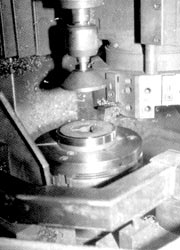 Figure 3: Pennsylvania Pressed Metals found that they could turn and face the part while holding it by its splined ID. |
|
As an alternative to our original fixturing plan, we decided to hold the part by the splined ID. We machined the 76.2mm high jaws on our 3-jaw chuck to hold the part by the splined diameter (Figure 3).
The splined ID afforded less workholding surface area because of the splines, and it was much shallower than the larger ID, so we were concerned that the fixturing would be inadequate. We restarted the OD machining operation with reduced speeds and feeds, fearful that the part would spin and break the insert. Chucking pressure was set at 14 kgf/cm2.
This time we were pleasantly surprised. The first cut produced good results, with no part spinning on the mandrel and no broken insert. We gradually worked our way back to a speed of 228.750m/min. and a feed of 0.078 mm/rev. Parts produced with this speed, feed, and workholding method met print specifications. We now had the part half machined.
Having found the proper tooling and workholding, we didn’t have as many obstacles to overcome when we turned our attention to boring the larger ID. The 3-jaw chuck was bored out to accept the part OD. The same 80° diamond-shaped, PCBN-tipped tool was used in a boring bar. Chucking pressure, speed, and feed were the same as the previous OD machining operation. The larger ID’s depth, diameter, gage point, angles, overall length (OAL), and runout specs were all maintained. At this stage of sample production, we felt the production process was established. After switching the work to a Mori-Seiki SL-3 CNC lathe, which was more suited to heavy-duty turning, we thought we were ready to make parts (Figure 4).
|
|||||||||||||||||||||||||||||||
| Figure 4: The increased capacity of the Mori-Seiki machine, as indicated by this table, made it more suitable for hard turning. |
The Coolant Question
It wasn’t until we were into production that we got our third surprise. As we began making parts, we found the PCBN-tipped inserts we used in the boring operation were breaking and tool life was dropping. We ran two tests to determine if coolant applied to the tool was the problem.
Test 1 was to apply as much water-soluble coolant as possible through the turret and at the tool/workpiece interface. Several inserts were used to compile data for tool life.
The same quantity of inserts was used in Test 2, but without coolant. When tool life was evaluated between Test 1 and Test 2, we found that the tools in Test 2 lasted 20% longer. We concluded that thermal shock was causing the tools to wear and break more quickly in Test 1. We suspected that even with the large amount of coolant being applied, coolant flow was being cut off intermittently, because the rotation of the chuck and chip flow were disrupting coolant flow. At this point, we chose to run the turning and boring operations dry.
Gaging Changes
Our last series of surprises came as we tried to measure the parts. The micrometers we initially used to measure the OD and bore depth and the go/no go gages we used to measure the larger ID proved ineffective. We first tried to measure the OD with a 101.6mm to 127.0mm micrometer, but our operators found it difficult to get an accurate reading while handling the micrometer and the part at the same time. Because of this awkwardness, gage repeatability and reproducibility (R&R) was an unacceptably high 40%.
After exploring other methods to measure the OD, we decided to use a snap gage of the same size as the micrometer. The gage’s C frame and indicator were mounted on a base plate, eliminating the need for the operator to juggle the gage and part at the same time. Unlike the micrometer, this gage could be preset to the desired feature measurement. We could then determine the machine tool adjustments required to bring parts within the size specifications indicated by the gage settings.
However, we couldn’t accurately size the parts until we solved the problems caused by excessive heat retention. A dry turning operation with PCBN inserts generates considerable heat. Most of this heat is evacuated with the chips; when we first tested the PCBN inserts without coolant, we noticed a red-hot stream of chips flowing off the tool. But some heat is retained in the part. In this operation, part temperatures were as high as 54.4°C (130°F) after machining. This much heat caused the part to expand. After cooling to 20.0°-22.2°C (68°-72°F) the part would shrink, causing its actual room-temperature size to be 0.041mm less than the size it was gaged at in the shop. The size difference represented 82% of the available tolerance.
Parts that we may have gaged and passed while they were still warm were being rejected by the customer when it gaged them after they had cooled to room temperature. Waiting for the parts to cool before gaging them at our shop was not a solution, because the delay would have slowed down our production process, and gaging that long after machining would not have alerted the operator to a problem soon enough. By the time he would have determined the extent of the problem, several more scrap parts would have been made.
We tried to cool the part in a vat of coolant before gaging to provide feedback to the operator in a more timely manner, but the results varied too much. Because we could not maintain a consistent temperature or cooling rate, shrinkage before gaging deviated from part to part. Adding a cooling coil (Figure 5) and a Vortec cabinet cooler stabilized the cooling process but did not control all the variables.
The most effective and reliable method we found to measure the OD was with the use of a temperature-sensing and -compensating gage head. This instrument told us what the part’s actual dimensions would be at room temperature regardless of the part’s temperature at the time of gaging. The consistency with which operators could measure parts with this type of gage was reflected in the gage R&R, which was 8% with the compensating gage head. Because parts could be gaged quickly and accurately, the machine’s CNC could be reprogrammed before it produced a large number of scrap parts.
The bored larger ID was originally measured with a go/no go plug. We weren’t able to ascertain variable data for CNC machine offsets, and the size and weight of the part made accurate gaging difficult. So we switched to a three-point contact gage. With the contact gage, operators were able to achieve a 5% gage R&R.
We also had to measure the larger ID’s depth to determine if it was machined to specifications. We initially used a micrometer to measure the depth. However, difficulties in handling the micrometer resulted in a gage R&R of 22%. A digital indicator mounted on a column and a granite block resulted in an acceptable gage R&R of 6%.
Our operators found it equally awkward to measure the OAL with a micrometer. With this method, they achieved a gage R&R of 23.5%. When they began measuring OAL with the same digital indicator, column, and granite block they were using to measure the larger ID’s depth, however, they were able to obtain a desirable gage R&R and increase efficiency by combining two quality checks in one instrument.
Another gaging challenge was measuring the position of the 30°15' to 30°45' angle from a gage point of 53.124mm to 53.175mm and 41.224mm to 41.275mm. As shown in Figure 1, this angle was located on the larger ID and was relative to the part centerline and a point in space located from the ID face. Relying on the repeatability of the CNC machine, we decided to triangulate the coordinates and measure the larger ID’s diameter, depth, and angularity. By holding the larger ID to its specified diameter and depth and the bevel on the ID to its specified angularity, the gage-point dimensions could be assured.
While our first attempt at hard turning was a very long and difficult learning process, we gained experience that was vital to our success in producing the PM differential gear rings. The first 2000 pieces took six months to produce; today, we produce 2000 pieces in 48 hours.
During the production process, we overcame many obstacles through trial and error. We resolved other problems by applying information we acquired in trade journals, seminars, technical papers, and conversations with people who had experience. We hope that our experience will propel others to success in hard turning PM.
About the Author
Kevin Ackman is supervisor of the secondary finishing department and Thomas Farley is manager of personnel development and education with Pennsylvania Pressed Metals Inc., Emporium, PA.
Related Glossary Terms
- arbor
arbor
Shaft used for rotary support in machining applications. In grinding, the spindle for mounting the wheel; in milling and other cutting operations, the shaft for mounting the cutter.
- boring
boring
Enlarging a hole that already has been drilled or cored. Generally, it is an operation of truing the previously drilled hole with a single-point, lathe-type tool. Boring is essentially internal turning, in that usually a single-point cutting tool forms the internal shape. Some tools are available with two cutting edges to balance cutting forces.
- boring bar
boring bar
Essentially a cantilever beam that holds one or more cutting tools in position during a boring operation. Can be held stationary and moved axially while the workpiece revolves around it, or revolved and moved axially while the workpiece is held stationary, or a combination of these actions. Installed on milling, drilling and boring machines, as well as lathes and machining centers.
- chuck
chuck
Workholding device that affixes to a mill, lathe or drill-press spindle. It holds a tool or workpiece by one end, allowing it to be rotated. May also be fitted to the machine table to hold a workpiece. Two or more adjustable jaws actually hold the tool or part. May be actuated manually, pneumatically, hydraulically or electrically. See collet.
- clearance
clearance
Space provided behind a tool’s land or relief to prevent rubbing and subsequent premature deterioration of the tool. See land; relief.
- computer numerical control ( CNC)
computer numerical control ( CNC)
Microprocessor-based controller dedicated to a machine tool that permits the creation or modification of parts. Programmed numerical control activates the machine’s servos and spindle drives and controls the various machining operations. See DNC, direct numerical control; NC, numerical control.
- coolant
coolant
Fluid that reduces temperature buildup at the tool/workpiece interface during machining. Normally takes the form of a liquid such as soluble or chemical mixtures (semisynthetic, synthetic) but can be pressurized air or other gas. Because of water’s ability to absorb great quantities of heat, it is widely used as a coolant and vehicle for various cutting compounds, with the water-to-compound ratio varying with the machining task. See cutting fluid; semisynthetic cutting fluid; soluble-oil cutting fluid; synthetic cutting fluid.
- edge preparation
edge preparation
Conditioning of the cutting edge, such as a honing or chamfering, to make it stronger and less susceptible to chipping. A chamfer is a bevel on the tool’s cutting edge; the angle is measured from the cutting face downward and generally varies from 25° to 45°. Honing is the process of rounding or blunting the cutting edge with abrasives, either manually or mechanically.
- feed
feed
Rate of change of position of the tool as a whole, relative to the workpiece while cutting.
- flat ( screw flat)
flat ( screw flat)
Flat surface machined into the shank of a cutting tool for enhanced holding of the tool.
- grinding
grinding
Machining operation in which material is removed from the workpiece by a powered abrasive wheel, stone, belt, paste, sheet, compound, slurry, etc. Takes various forms: surface grinding (creates flat and/or squared surfaces); cylindrical grinding (for external cylindrical and tapered shapes, fillets, undercuts, etc.); centerless grinding; chamfering; thread and form grinding; tool and cutter grinding; offhand grinding; lapping and polishing (grinding with extremely fine grits to create ultrasmooth surfaces); honing; and disc grinding.
- hard turning
hard turning
Single-point cutting of a workpiece that has a hardness value higher than 45 HRC.
- hardness
hardness
Hardness is a measure of the resistance of a material to surface indentation or abrasion. There is no absolute scale for hardness. In order to express hardness quantitatively, each type of test has its own scale, which defines hardness. Indentation hardness obtained through static methods is measured by Brinell, Rockwell, Vickers and Knoop tests. Hardness without indentation is measured by a dynamic method, known as the Scleroscope test.
- inner diameter ( ID)
inner diameter ( ID)
Dimension that defines the inside diameter of a cavity or hole. See OD, outer diameter.
- lapping compound( powder)
lapping compound( powder)
Light, abrasive material used for finishing a surface.
- lathe
lathe
Turning machine capable of sawing, milling, grinding, gear-cutting, drilling, reaming, boring, threading, facing, chamfering, grooving, knurling, spinning, parting, necking, taper-cutting, and cam- and eccentric-cutting, as well as step- and straight-turning. Comes in a variety of forms, ranging from manual to semiautomatic to fully automatic, with major types being engine lathes, turning and contouring lathes, turret lathes and numerical-control lathes. The engine lathe consists of a headstock and spindle, tailstock, bed, carriage (complete with apron) and cross slides. Features include gear- (speed) and feed-selector levers, toolpost, compound rest, lead screw and reversing lead screw, threading dial and rapid-traverse lever. Special lathe types include through-the-spindle, camshaft and crankshaft, brake drum and rotor, spinning and gun-barrel machines. Toolroom and bench lathes are used for precision work; the former for tool-and-die work and similar tasks, the latter for small workpieces (instruments, watches), normally without a power feed. Models are typically designated according to their “swing,” or the largest-diameter workpiece that can be rotated; bed length, or the distance between centers; and horsepower generated. See turning machine.
- mandrel
mandrel
Workholder for turning that fits inside hollow workpieces. Types available include expanding, pin and threaded.
- micrometer
micrometer
A precision instrument with a spindle moved by a finely threaded screw that is used for measuring thickness and short lengths.
- outer diameter ( OD)
outer diameter ( OD)
Dimension that defines the exterior diameter of a cylindrical or round part. See ID, inner diameter.
- polycrystalline cubic boron nitride ( PCBN)
polycrystalline cubic boron nitride ( PCBN)
Cutting tool material consisting of polycrystalline cubic boron nitride with a metallic or ceramic binder. PCBN is available either as a tip brazed to a carbide insert carrier or as a solid insert. Primarily used for cutting hardened ferrous alloys.
- rapid traverse
rapid traverse
Movement on a CNC mill or lathe that is from point to point at full speed but, usually, without linear interpolation.
- tolerance
tolerance
Minimum and maximum amount a workpiece dimension is allowed to vary from a set standard and still be acceptable.
- toolholder
toolholder
Secures a cutting tool during a machining operation. Basic types include block, cartridge, chuck, collet, fixed, modular, quick-change and rotating.
- turning
turning
Workpiece is held in a chuck, mounted on a face plate or secured between centers and rotated while a cutting tool, normally a single-point tool, is fed into it along its periphery or across its end or face. Takes the form of straight turning (cutting along the periphery of the workpiece); taper turning (creating a taper); step turning (turning different-size diameters on the same work); chamfering (beveling an edge or shoulder); facing (cutting on an end); turning threads (usually external but can be internal); roughing (high-volume metal removal); and finishing (final light cuts). Performed on lathes, turning centers, chucking machines, automatic screw machines and similar machines.