Grinding With Segments: Heavy Stock Removal Guide
Segmented grinding wheels can help in heavy stock-removal applications with large contact areas.
Quick take: Grinding segments matter when stock removal, heat, and contact area make ordinary wheel choices less effective. This article works best when it is read with stability and process-control references rather than treated as a simple wheel-selection note.
Related references: Using Stability Lobe Diagrams to Control Chatter, Shop math: Practice makes perfect, and Understanding Cutting Equations for Feeds and Speeds.
Without segmented abrasives it might be impossible to grind large parts flat and parallel using a vertical-spindle surface grinder. Smaller parts can be ground with smaller vertical surface grinders using cylindrical grinding wheels, but the weight of a wheel larger than 2′ in diameter would make it an unwieldy burden for an operator to lift and position on the machine every time the wheel needed changing.
With segmented abrasives the operator can mount the abrasive one piece at a time. The chuck holds the pieces in a circular arrangement. The smaller pieces are much easier to handle, and in arrangements that leave spaces between the segments, the spaces provide chip clearance. These segments are used in machines with reciprocating or rotating worktables.
To keep costs low and productivity high when using abrasive segments, shops must realize that surface grinding with segmented abrasives is not the same as grinding with a wheel. Typically, shops use segment grinding for heavy stock removal prior to the fabrication or assembly of a part. There is usually a large area of contact between the wheel and the workpiece. The heavy stock removal and large contact area quickly wear the segments down. As a result, the ratio of the volume of metal removed to the volume of abrasive used (commonly called the G-ratio) is often low. Any small change that can increase this ratio will be well worth the effort, especially in production operations where every improvement is compounded over the long run of parts.
A Matter of Choice
The first step in the cost-effective use of segmented abrasives is selecting the right abrasive for the application. Segments are available in hundreds if not thousands of shapes and a variety of specifications. Some are shaped like pie wedges and, when fitted together, form a wheel shape. They may even be made with tongues and grooves so they can be locked together. But not all segments are manufactured as sections of a wheel. The shape a shop will need depends on the shape the grinding machine chuck accepts. The most common segment shapes in North America are for chucks from Cortland, Blanchard Bonus Grind, Norton Mattison, Abrasive Associates (Ferro Corp.), and Sterling. With the increase in imported and specialty machines, such as Gockel and Reform grinders, segment manufacturers are introducing smaller segment shapes to fit their chucks.
Segments often contain coarse grit and a high degree of porosity so that they can cut where there is a high wheel-to-work contact area. Although each segment manufacturer has its own way of marking its products, a typical designation tells the user the segment’s abrasive type, grit size, grade, structure, and bond. A typical specification for a segment from Norton Co., Worcester, MA, might read: 32A30-G12VBEP. The “32A” tells the user what type of abrasive it is. In this case, it is an aluminum-oxide (Al2O3) segment; a “C” in place of the “A” would indicate that this is a silicon-carbide (SiC) segment. For Norton’s products, the higher the number, the more open the wheel is. The “30” is the abrasive’s grit size. “G” is the abrasive’s grade and “12” is the structure. The last four characters are the segment’s bond type. The “V” in this part of the specification means that this segment has a vitrified bond.
Abrasives used in segments range from the very friable to the very durable. When choosing an abrasive, the user must take into account the type of material being ground, its tolerance to heat, and the level of productivity needed. It would be a mistake for a shop to focus solely on the cost of the segments when choosing an abrasive. Using the least expensive segment does not always ensure the lowest per-piece grinding cost. For example, many segment users prefer dark Al2O3products, because they are very inexpensive. But these abrasives are often the most expensive to use, because their G-ratios are extremely low and they wear quickly. By contrast, sol-gel ceramic-type abrasives can cost two to three times as much as their Al2O3 counterparts, but they can yield dramatic increases in productivity because of their ability to cut hard-to-machine materials without wearing quickly. For any given application, the ideal abrasive is not the least expensive, but the abrasive that will cut until dull without breaking up or falling out of the bond prematurely.
For most steels, Al2O3 is the abrasive of choice. The least expensive of the fused (synthetic) Al2O3 abrasives commonly used in segments is tough, blocky, and dark. (Norton’s designation for it is 57A). Going up the scale in terms of cost is the intermediate dark-and-white blend (53A), which is also known as “salt and pepper;” friable white (38A); friable pink (25A); semi-friable pink/purple (86A); and strong, sharp, monocrystalline gray (32A). Users should note that the segment’s color typically is determined by the pigmented bonding material that is used, not the abrasive type. For example, a white Al2O3 segment actually may be one of any number of colors depending on its bond.
Sol-gel abrasives are most commonly used with difficult-to-grind steels that contain carbides, because the abrasive grains are harder and stronger and exhibit more fracture toughness than conventional abrasives. The abrasive works by a self-sharpening mechanism that allows for increased performance at a high metal-removal rate (mrr). Because of its hardness and resistance to fracture, the abrasive holds up well when grinding very hard materials. Sol-gel abrasives are especially popular in production operations. Their superior properties are the result of a highly controlled manufacturing process. The level of engineering required in their manufacture also accounts for their higher cost. Manufacturers almost always blend sol-gel abrasives with conventional Al2O3 for optimal performance. In Norton’s sol-gel specification, the number preceding the abrasive code indicates the ceramic’s concentration level. The higher the number, the higher the concentration.
SiC abrasives are characterized by very hard, sharp, friable grains. They are generally the best choice for grinding low-tensile gray iron, chilled iron, cast iron, soft bronze, brass, copper, aluminum, and nonmetallic materials. When used on these materials, SiC exhibits good workpiece penetration with little loading. Black SiC (Norton’s 37C) is the most commonly used, while green SiC, which is more pure, may perform better in applications where maximum grain sharpness and durability is necessary.
For the highest mrr, users should grind with 24- or 30-grit segments. With an appropriate sparkout, operators will be able to achieve a visual finish using these grits. A finer abrasive such as 36- or 46-grit abrasive might be needed to achieve a very fine finish or to grind a difficult-to-machine metal that coarse abrasives cannot penetrate readily. These difficult materials include hardened tool steels and some types of stainless steel. To achieve very fine finishes or to machine especially difficult materials, manufacturers supply segments in grit sizes up to 180. Grit sizes coarser than 24 are usually not used, because the grains’ low surface area gives the bond little to hold on to.
| Machine Tool Factors Available horsepower Available speeds, feeds Table size Total segment area Coolant type, pressure, flow Machine rigidity Flatness of worktable Work-Material Factors Segment-Selection Factors Operational Factors |
| Table 1: The factors that influence the performance of a segment grinding application. |
Hold the Abrasive
Segments are available with a variety of bonds. Vitrified-bond segments are the most common, because they offer the longest segment life. But organic segments might be specified to avoid heat damage when grinding very thin parts or small sections that cannot tolerate warpage. Resin-bond segments also are available.
Vitrified bonds are categorized by grade, which refers to the amount of bonding material present in the segment. The softer the grade, the less bond in the segment. Most shops using segmented abrasives specify a very soft grade to handle the high contact area that typically exists between the segments and the workpiece. The most commonly used segment grades are E, F, and G. These grades are ideal for mild steels such as A-36, 4140, and 1020. Generally, the more difficult a material is to grind, the softer the grade of bond that should be used. The next most common grades after E, F, and G are D, H, and I. Extremely soft D-grade segments are ideal for tool steels, whereas the harder H and I grades are typically used for cast iron or to grind mild steel with high-horsepower grinders. Plus grades are often quite useful in the soft end of the grade range, where differences in grade are larger. Shops might use a much harder grade in specialty applications.
Most segment bonds have an open and highly porous structure for chip clearance and to reduce cutting temperatures. For operations such as knife grinding, where the area of contact is narrow, or for work materials such as tool steel that must be ground with a high concentration of cutting edges, standard-structure segments might be called for.
A segment with a porous structure will grind as if it were 11¼2 to two grades harder. If a shop is converting from a standard structure to an open structure, it must specify a grade as much as two letter grades lower to obtain the same power draw from the machine. For instance, an application that takes a grade-12 standard-structure segment would require a grade-8 open-structure segment.
Performing to Expectations
Even though segments are typically used for roughing, which involves heavy stock removal and low-tolerance cutting, shops can still closely monitor and control the segments’ performance. Operators often develop their own techniques and product preferences based on what has worked for them in the past. However, to compete in today’s marketplace, shops must constantly evaluate their current practices to determine if they can be improved with emerging technology.
 |
| Table 1: The factors that should be considered and measured at each stage in a segment grinding application. |
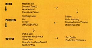
In its evaluation of a process, a shop must look at all aspects of the grinding system. The inputs that influence the performance of the system can be organized into four broad categories: machine tool factors, work-material factors, segment-selection factors, and operational factors (Table 1). To improve a process, a shop must understand how each set of factors affects the system’s output.
The grinding process is the result of the interactions between these factors. A segment grinding process consists of the observable, measurable qualities of grinding power and energy and a multitude of unobservable, microscopic interactions that result in process output (Figure 1). It would be impossible to examine all of the factors that influence a grinding system’s performance within the scope of this article, but we can focus on a few key areas and how they might be improved.
Taking stock of the existing process is the first step toward better performance. This analysis should include a careful measurement of current output. The output of the system after a change has been made can be compared to this baseline data. If productivity improves after a change, this comparison will provide a quantifiable justification for making the modifications permanent.
A shop can evaluate its segment performance either by conducting a controlled short test, which will provide results quickly and can be done readily for some operations, or by collecting data during usual production. The second method takes longer, but it will not interrupt production.
For the short-term test, an operator takes precise data under ideal conditions. To gather sufficient data, the operator will need an ample supply of workpieces of similar geometry and material type. He will also need to remove a measurable amount of material from each part. Once the operator has mounted and dressed the segments, he grinds with them for a specified period of time for break-in. For each test run, the operator should record:
- The segment specification;
- The surface area per segment;
- The total number of segments used in the set held by the chuck;
- The total segment area (surface area per segment 5 number of segments in set);
- The area of one workpiece;
- The total number of workpieces loaded into the machine;
- The total area of the load;
- The rate of downfeed;
- The table speed.
Once the test part or parts are on the machine, all high and low spots on the segments and the parts should be ground out so that full contact between the segments and the parts’ surfaces is achieved. If this is not done, it will be impossible to determine the total amount of stock removed during the test.
Next, the operator downfeeds for a measured amount. A good downfeed for these tests is 0.100″. This grinding is performed without a sparkout cycle. After the grinder has reached the determined downfeed, the operator measures the linear amount, or thickness, of the metal removed. The total grind time can be measured, or it can be calculated from the downfeed rate. The number of segment dresses, the reasons for the dresses, and the power draw or percent load on the machine should be recorded as the test grinding proceeds. Linear segment wear can be measured or calculated using the following formula:
| Approximate Linear Segment Wear = Total Downfeed – Linear Metal Removed |
The volume of stock removed from each test part and segment wear can be calculated by taking the linear amount removed from the workpiece or segment and multiplying this number by the area of the respective workpiece or segment as follows:
| Volume of Metal Removed = Linear Metal Removed 5 Total Area of Parts Ground Volume of Segment Used = Linear Segment Wear 5 Total Segment Area |
With this data, the following results can be calculated:
| G-ratio (Volumetric) = Volume of Metal Removed / Volume of Segment Used Rate of Removal = Volume of Metal Removed / Total Grind Time |
Costs can be calculated as follows:
| Cost of Segment Set = Cost per Segment 5 Number of Segments in Set Usable Abrasive Height = Segment Height – Stub Size Volume of Usable Abrasive = Usable Height 5 Total Segment Area per Set Cost of 1 Cu. In. of Abrasive Wear = Cost of Segment Set / Volume of Usable Abrasive Cost of Total Abrasive Wear = Volume of Abrasive Wear 5 Cost of 1 Cu. In. of Abrasive Wear Machine Cost = Machine Cost in Dollars per Minute 5 Total Grind Time Total Machine Cost (With Segment Wear) = Cost of Abrasive Wear + Machine Cost Cost to Remove 1 Cu. In. of Stock = Total Machine Cost / Volume of Metal Removed |
Once this data is recorded for all of the different segment types, grades, downfeed rates, and other conditions being tested, the total costs, rather than per-segment costs, can be compared. This comparison will reveal the optimal parameters for the process.
To gather data in production, a shop can choose from a variety of methods. One of the easiest ways to keep track of abrasive performance in high-production grinding operations is to record the weight of parts both before and after grinding and the size and number of the discarded segment stubs. With this information, a G-ratio for the operation can be developed according to the following formula:
| G-ratio = (Total Weight in Lb. of Metal Removed / Average Density of the Work Material in Lb. per Cu. In.) / (Linear In. of Segment Used 5 Number of Segments per Set 5 Segment Area in Sq. In.) |
The G-ratio of the existing operation should be recorded over a period of time. A month’s data should be sufficient. To test an alternate specification that shows promise, the operator makes the change and then tracks the data using the same method. A comparison of the data will show whether or not the new operation is cost effective from an abrasive standpoint. For a shop to determine if the operation is more efficient, the operator should divide the total weight of metal removed by the total machine hours for the operation before and after the change and compare calculations.
|
| Table 2: These test results compare the performance of 5SG30-F12VSP sol-gel abrasive segments to 32A46-F12VBEP Al2O3 segments when grinding D-2 steel in its hardened and unhardened states. The abrasives were used on an 84″ Blanchard machine with a 0.024 ipm downfeed. |
Reducing Costs
Once a shop has determined how it will evaluate its current process and any changes it makes, it must then consider what improvements are needed. As a guide, the shop’s personnel might keep in mind these principles of vertical-spindle surface grinding:
For maximum productivity, maximize metal removal. Use the highest downfeed rate that will not cause severe segment breakdown or machine overload. Consider using premium abrasives. To control costs when productivity is not as critical, grind at rates that save money based on the machine costs and the material being ground.
Place as many parts on the table as possible. When many parts are being ground, use the outside of the table before the inside.
Use coarse grit sizes such as 24 or 30 whenever possible. Use sparkout to obtain required finish.
Select the hardest grade that will not burn or warp the workpiece or cause machine power overload.
In its search for practices to improve, a shop should also look for inappropriate or excessive dressing or the discarding of segments before the end of their usable life. Avoiding these wasteful mistakes can save a large production operation thousands of dollars per year.
Labor costs can be reduced by minimizing the number of setups and segment changes. Often, the time between segment changes can be increased by switching to a segment with a greater height, assuming there is still clearance between the segments and the workpiece. This increases the percentage of usable abrasive per segment. When longer-grinding premium segments are used, the abrasive cost per part can be reduced as well as the cost of labor to mount the segments.
When a shop desires higher productivity even after it has optimized its segment grinding process, it should consider alternatives such as sol-gel abrasives. Although these abrasives cost significantly more than conventional abrasives, shops can still save money in overall grinding costs when sol-gels are used to achieve high removal rates on tough-to-grind materials. Sol-gels used correctly can provide G-ratios that are three or more times the G-ratios of the best conventional abrasives. The segments cut with less power, permitting the use of higher downfeed rates. And because the segments last longer, there are fewer segment-set changes.
Sol-gel segments may not perform significantly better when they are used to grind soft materials, however. If there is some question about the ability of sol-gel segments to improve a particular application, a shop should test first. In some cases, the test will show that the use of sol-gel segments is still justified. Figure 2 shows such a case. The results in Figure 2 are a comparison in total costs, which are defined as the labor and machine costs to remove 1 cu. in. of material. These test results indicate that a shop would be justified in replacing 32A segments with sol-gel segments in an operation grinding D-2 steel parts whether the D-2 was in a hard or soft state.
In the drive to eliminate all unnecessary costs, shops are looking closely at their grinding operations. Already, parts are coming to the grinder closer to final dimension to reduce the amount of grinding necessary. But this is not enough in today’s competitive atmosphere. To succeed in this climate, shops must be willing and able to analyze, quantify, and change their processes to achieve maximum productivity.
About the Authors
Nancy Narbut is an engineer, Tom Stafford is a technician, and John Tartaglione is business-unit manager for Norton Co., Worcester, MA.Glossary terms in this article

MFGAxis Discussion