Grinding: A pictorial odyssey
An examination of the grinding process through the lens of an electron microscope.
An examination of the grinding process through the lens of an electron microscope.
A picture is worth a thousand words, and that maxim holds true for grinding. The interactions between the abrasive grit and the workpiece occur at a microscopic level and can be hard to visualize. When I give my “High Intensity Grinding Course,” I’ll explain a subject for 5 minutes and watch attendees eyes start to glaze over. But when I flash a photo on the screen—Boom!—I see the “aha” in their eyes as they instantly form a mental picture of what I’m talking about.
Over the years, I’ve taken and collected hundreds of electron-microscope photos of grinding wheels, swarf, workpieces, dressing tools and just about everything else related to grinding. I’ve selected 22 of the best and assembled them here, presented with descriptions of the photos and interesting facts or trivia about grinding.
Courtesy of Niagara Cutter
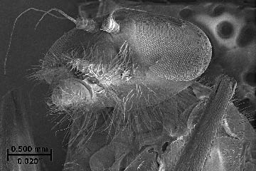
Figure 1: The head of a housefly. The hairs on the fly’s legs are 3μm thick, about the same thickness as a chip produced when grinding hardened steel. The fly’s eyes are each 0.700mm in diameter, about the same size as a 24-mesh abrasive grit.
Courtesy of J. Badger
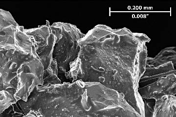
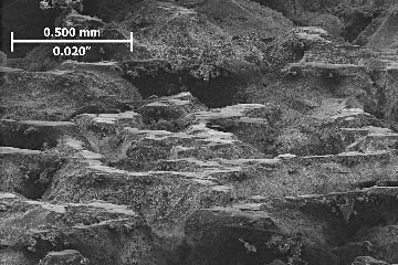
Figure 2: Sharp grits in a freshly dressed, 80-mesh, vitrified-bond aluminum-oxide grinding wheel. An 80-mesh, 16 “-dia., 2 “-wide, 2 “-bore wheel contains about one billion abrasive grits.
Courtesy of J. Badger
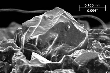
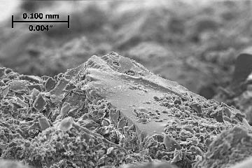
Figure 3: A single, 80-mesh Al2O3 grit in a freshly dressed vitrified-bond grinding wheel. A grit in a 16 ” wheel running at 3,000 rpm taking a 0.001 ” DOC is in contact with the workpiece 0.00008 seconds, or 0.08 milliseconds.
Courtesy of J. Badger
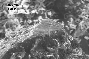
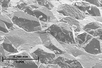
Figure 4: A dull grit in a worn, 46-mesh, vitrified-bond, N-grade, Al2O3 grinding wheel. Wheel dulling causes increased heat generation and grinding burn, increased normal forces and chatter and a finer surface finish.
Courtesy of J. Badger
Figure 5: Dull grits in a worn, 46-mesh, vitrified-bond, N-grade, Al2O3 grinding wheel. This wheel was excessively dull, and the wear flats were visible to the naked eye. This N-grade wheel was “too hard,” meaning it had too much bond material and dull grits did not break out of the bond.
Courtesy of J. Badger
Figure 6: The tip of a microfracturing ceramic grit in a worn, 46-mesh, vitrified-bond, Al2O3 Norton-SG wheel after grinding hardened steel. This grit has done a lot of work, but it is not dull. Because it is a microfracturing grit, the tip of the grit remained sharp, enabling it to cut material efficiently.
Courtesy of J. Badger
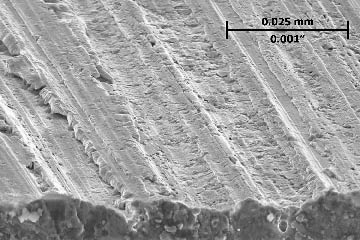
Figure 7: A ground and hardened steel surface. At the grit/workpiece interface there are three possible interactions: rubbing, side and front plowing and chip formation. Side plowing creates grinding scratches. This image shows plowing that caused the material to fold onto itself.
Courtesy of J. Badger
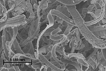
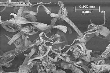
Figure 8: Swarf from grinding highly alloyed conventional HSS. Like turning and milling, grinding is a chip-formation process. However, the chips are thin and irregularly shaped. The swarf produced from grinding a standard ¼ “-dia., 4 “-long drill contains about 100 million individual chips.
Courtesy of J. Badger
Figure 9: A worn electroplated diamond wheel for grinding tungsten-carbide dies. This wheel was at the end of its life, but not wheel dulling is visible. The wheel experienced a large amount of grit fracture and bond fracture, and the cutting-point density increased to such a degree that the grits no longer effectively penetrated the workpiece.
Courtesy of J. Badger
Figure 10: Swarf from grinding a tungsten-carbide workpiece with a resin-bond diamond wheel. Even grinding carbide, or “hard metal,” is a chip-formation process. However, because of carbide’s higher hardness and lower ductility compared to steel, the chips are shorter and blockier. Almost all grinding operations form chips. The exception is ceramic material, which has such low ductility that the material-removal mechanism isn’t chip formation but rather brittle fracture. Ceramic material is removed when cracks form below the surface followed by the “beating out” of chunks of hard ceramic material above the cracks.
Courtesy of J. Badger
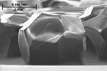
Figure 11: An 80/100-mesh diamond grit. Diamond and, in particular, cubic-boron-nitride abrasives can be manufactured in various geometries, from angular to blocky. This enables selection of geometries suited to particular grinding operations. The geometry shown is a truncated octahedron and is “blocky.” Therefore, it is suitable for grinding operations requiring high material-removal rates.
Review the print ads from this magazine to continue
This quick advertiser review unlocks the rest of the article and keeps the full-screen reader focused on the ads instead of the page chrome.

MFGAxis Discussion