Tuned tooling and tool-monitoring systems provide new ways to control and alter machining vibrations to make them contribute to, rather than detract from, successful metalcutting.
There’s no getting around the fact that any metalcutting operation creates vibrations in the tool, workpiece, and machine. But today’s technology allows machinists to keep these vibrations from spoiling the operation.
The vibration modulation inherent in machining results from the relationship between the cutting force and the relative displacement between the workpiece and the tool. This relative displacement affects chip thickness, which in turn varies the cutting force acting on the system. This sets up a feedback mechanism: Cutting forces depend on cutting parameters, the machining system responds to the cutting forces, and this response changes the cutting parameters. The end result is modulating vibration.
Engineers have used their understanding of machining dynamics to design monitoring systems that analyze the different modes of vibration utilizing real-time digital signal processing. These systems provide a viable method for suppressing tool vibration to maintain tighter tolerances and increase material-removal rates in all machining operations. This technology has also been applied as a way to monitor in process the condition of milling tools and provide control signals to minimize cutter, workpiece, and machine tool damage caused by runout (either an offset of the tool center from the axis of rotation or a failure of the plane of the cutter face to be perpendicular to the axis of rotation), tool loading, cutting-edge chipping, and breakage.
Three Modes
To effectively monitor and control the machining process, one must be able to distinguish between the three forms of vibration:
Free vibration, the tool’s response to initial conditions, is so-named because it occurs when the tool is free from externally applied forces. During the noncutting period in interrupted machining, the cutting force is eliminated and the tool springs back from its deflected position. In a stable machining process with structural damping, the amplitude of the relative vibration between the cutting tool and the workpiece will decrease with time, though the frequency or period of vibration will not change. Knowing the amplitude of the tool’s free vibration helps one determine the system’s dynamic characteristics. Free vibration is studied in modal analysis by hitting the tool with a known or measured force and measuring the resulting response. Knowing a system’s free-vibration amplitude allows one to discern the system’s dynamic character and predict its responses. In very precise finishing cuts, free vibration should be minimized.
Forced vibration is the machining system’s response to excitation and occurs at the same frequency as the excitation. Therefore, if the magnitude of the excitation remains fixed, the forced vibration’s amplitude will be constant over time. A common example of forced vibration is the radial tool displacement caused by imbalance and the resulting shaking force during rotation. The imbalance, or more precisely, the eccentricity of the center of gravity relative to the axis of rotation, will result in a once-per-revolution force whose magnitude is related to the speed of rotation squared. (Doubling the speed will quadruple the forced vibration’s magnitude.) One way to minimize this form of vibration in high-speed applications, before measuring it, is to employ well-balanced tooling.
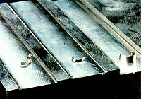
Slots machined in 7075-T6 aluminum with a 0.75"-dia., 6-diameter-long series endmill with 2 inserts. The standard endmill slot shown on the left demonstrated significant chatter at an axial depth of cut of 0.030". The tunable endmill run with the same machining parameters yields a highly stable process for the axial depth of cut of 0.030", as shown by the center slot.
Self-excited vibration is the machining system’s response feedback at work. In a self-excited system, a constant input force, such as the cutting force in a highly stable machining process producing continuous chips, may be modulated into a periodically varying response. Over time, depending on the stability of the system itself, the response amplitude may decay (remain stable), stay constant (remain marginally stable), or increase (become unstable). A common example of self-excited vibration, chatter, is usually caused by "regeneration waviness," in which each engaged cutting edge machines a surface made wavy by the preceding cutting edge. Regeneration waviness begins when entering the part - the tool goes from a noncutting to a cutting condition, resulting in transient vibration. A phase shift between the vibrating tool and the surface waves on the workpiece results in a variable chip thickness, which in turn may lead to further chatter.
Measuring these forms of vibration in a machining system allows the user to establish process-stability limits, determine various undesirable machining conditions, and specify optimum cutting conditions. Specially tuned tooling or dampers may be employed to correct undesirable conditions and achieve optimum cutting performance.
Tuned Tooling
By altering vibrations, a tuned tooling system (TTS) provides a means of increasing material-removal rates while maintaining tighter tolerances: When tuned correctly, longer tooling with greater length-to-diameter ratios can perform without undesirable vibration. A TTS may be applied to both rotating and stationary tools that are dynamically flexible, including boring bars, endmills, modular tooling, tool extensions, and long toolholders. A TTS combines dynamically tunable tools with a tuner system. The tunable tools include many commercially available damped tools and custom-made tools designed specifically for tight-tolerance applications. They do not include self-balancing, inertial disk, or rattler-type tools. The tools incorporate an internal mechanism that provides a controlled means of adjusting their dynamic characteristics. The mechanism forms a tunable damper that passively (using no internal electronics, measurement device, or active control) counteracts the tool vibration. Increased damping makes the tool act dynamically stiffer.
Figure 1: The performance range of tuned HSS boring bars of various length-to-diameter ratios. A 4:1 ratio is the base.
For maximum effectiveness, the tunable damper should be located as close as possible to the area that vibrates the most. The damper is usually built-in near the tool tip. Alternatively, a tunable damper might be placed in the cutting tool head, the toolholder or extension, or a modular toolholder section. Tunable dampers may also be designed to accommodate through-coolant tooling.
The internal tuned damping system is adjusted via a tuning screw, which alters the stiffness (and, therefore, the vibration frequency) and damping of the mechanism. This allows the damper to counteract the tool’s most flexible mode of vibration.
Although damped tooling designs have been around for decades, until recently there was no effective way to tune the tooling. But manufacturers today offer two-channel tuners that measure input and response signals and are compatible with all tunable tools. The tuner is a hand-held microprocessor-based signal conditioning and processing device. It’s designed to suppress tool vibrations over a broad range of frequencies (because different machine tools may exhibit vastly different vibration frequencies) and reduce free vibration in interrupted and finish machining. The tuner tunes the tool’s damping mechanism at or near the frequency exhibiting the maximum free vibration.
Using the tuner requires no understanding of dynamics, vibrations, or modal analysis. The tuner is about the size of a shoe box and has a small hammer and accelerometer connected to it. The tool is tuned while stationary within the spindle; no cutting tests or trial-and-error tuning are necessary. The user places a small sensor on the cutting end of the tool. He then taps the tool end lightly with an instrumented hammer. This provides both input and response signals. The tuner reads the signals and tells the user which way to adjust the tuning screw. When the tool is optimally tuned, the user locks the tuning screw and removes the sensor. The tool is ready for use. This tuning procedure is required only periodically and can be easily incorporated into standard tool-management schedules. Generally, a tool will stay in tune even when it is removed from the toolholder.
The predicted performance of a tuned tool compared to a standard tool depends on how stable the machine tool and workpiece dynamics are. The typical performance range of a tuned HSS boring bar with a length of 4 diameters is depicted in Figure 1. The horizontal line that intersects the standard tool-performance line and the upper and lower boundaries of the tuned tool-performance region indicate the length-to-diameter ratios that will provide equivalent stability and chatter limits. As shown, a tuned boring bar 7 to 9.5 diameters long performs as well as a much shorter standard, untunable bar 4 diameters long. The enhanced stability of tunable tools with longer length-to-diameter ratios translates to additional machining capacity.
The vertical line in Figure 1 indicates the maximum depth of cut (DOC) a cutter can achieve without chatter. A tuned boring bar can remove 500% more material without chatter than a standard bar with an equivalent length-to-diameter ratio can remove. The tunable tool’s enhanced stability offers a means of increasing material-removal rates and decreasing cycle times. Furthermore, the reduced chatter results in higher quality cuts, tighter tolerance capability, reduced postprocessing, and longer tool life.
In terms of price, a TTS may cost about 50% more than standard untuned tooling, but since the damper and tuner are nonperishable, a TTS can achieve a significant return on investment.
Tuning the Untunable
A TTS may also be used with standard, untunable tools to establish speeds that will ensure maximum stability and chatter resistance. A digital readout displays the preferred speeds in rpm. The user may cycle through these speeds until he finds one that is within the machine’s speed range and is appropriate for the tool material and workpiece material.
In the following example, a TTS was used to help select the preferred speeds for a standard, untunable, 8-insert, 7.5"-dia. milling cutter mounted on an 11.5"-long, 2.2"-dia. extension in a horizontal machining center equipped with a CAT-50 taper. The workpiece was a gray-cast-iron bulkhead. Initially, the cutting speed for this application was set at 1000 rpm, but at this speed, due to the flexible nature of the tool, the result was chatter and broken inserts. To limit the amplitude of the chatter, the cutter was run at a speed of 130 rpm, a feed of 2 ipm, and DOCs of less than 0.049". These parameters led to unacceptably long cycle times and low production rates.
The TTS was used to perform an analysis determining the tool’s stability and chatter resistance at various speeds. Figure 2 shows the resulting stability characterization. Areas that lie above the lobes are unstable, while regions below the lobe boundaries yield stable machining operations. The preferred speed results in phase-locked vibration, which eliminates the regenerative chatter mechanism of self-excited vibration. As Figure 2 indicates, 1,400 rpm is the most preferred speed. Of all stable speeds (represented by the wider lobe), 1,400 rpm allows for the deepest cut. The first lobe is preferred because of its greater width (stable speed range), higher stability limit, and the corresponding increase in production rates. The feed rate was increased proportionally to the speed increase. Figure 2 also illustrates how unfortunate the original speed specification of 1,000 rpm was. The specification was made without taking into account the dynamics of the system. Overly conservative correction limited productivity without providing a viable solution.
Figure 2: The stability of an untunable, 8-insert milling cutter is represented here in terms of axial depth of cut over a rotational speed range. Areas above the lobes are unstable, while those below the lobes yield stable machining. This graph was output by a TTS based on internal analyses.
The preferred speed selection took less than 5 minutes. An operator made the selection during a break.
The TTS also incorporates a microphone input that allows the operator to measure the noise emitted (airborne vibration) from a machine experiencing chatter. The dominant frequency in the spectrum of the measured noise signal indicates the most flexible dynamic mode of vibration. Without calculating the limit width of cut, the tuner, based on the number of cutting edges at a specific axial location on the tool, displays preferred speeds that correspond to the location of stable regions between the lobes. If the preferred speed displayed matches the actual rotational speed of the tool, then the process is either stable and the measured frequency corresponds to the tooth impact frequency, or the process is highly unstable with a width of cut exceeding the stable limit.
Monitoring Milling Tools
An in-process tool-monitoring system (TMS), designed specifically for milling tools with 2 to 64 cutting edges, can detect cutter runout, chipping, and sudden breakage. It then issues alarm codes and a feed-hold control signal within one tool revolution at speeds up to 12,000 rpm. A TMS is used for dedicated applications in which one milling tool remains in the spindle, or it may be integrated with macro programs in a machining center CNC to provide multiple-milling-tool monitoring.
A TMS employs a microprocessor-based signal conditioning and processing unit and two accelerometers externally fixed to the machine tool to measure vibration signals generated by the impact of cutting edges contacting the workpiece. Condition thresholds are self-calibrating and dynamically established in-process, providing high sensitivity even under continuously varying cutting conditions and material properties. Normally, a monitoring system must be "trained" - that is, typical responses to varying conditions must be recorded to establish high- and low-range offsets as acceptable condition limits. This technique is effective when monitoring is limited to detecting the presence of a tool, as in drilling and tapping, but it is often plagued with false and missed detection, especially in milling operations.
In-process threshold determination eliminates the need for this training and allows the system to monitor limitless cycle durations and workpieces of varying hardnesses without system modification. The user may customize monitoring sensitivity for runout and tool chipping to reflect tool conditions he deems acceptable, based on application requirements and the user’s own tool-management practices.
Figure 3: Features indicating breakage of an undamaged cutter (a), a damaged cutter (b), and sudden insert failure (c). The entry cut was made with a 4"-dia. facemill with 8 Si3N4 inserts run at 1,500 rpm, 72 ipm, 50% radial immersion, 0.060" axial depth in cast iron.
If a machine tool exhibits flexibility and vibration levels that limit accurate machining, then the resolution of the tool-condition monitor typically is limited as well. A TMS can more sensitively monitor a machine tool that holds tighter tolerances.
As illustrated in Figures 3a and 3b, a TMS can enhance and distinguish characteristic features indicative of runout, chipping, and breakage. The existence of a single broken insert in a milling cutter results in a larger vibration response (12% to 15%) than an undamaged cutter. When compared to idle vibration and additional noise present during cutting, this nominal difference is insufficient to permit consistent recognition of tool damage without an excessive amount of false detection or the need for a catastrophic level of tool failure prior to detection. A TMS distinguishes the cutting-edge damage from all other signals found in normal milling conditions, which have a lot of raw vibration signals. This permits detection in time to limit damage to the tooling, workpiece, and machine tool. Sensitive monitoring does not result in false detection even under continuously varying cutting conditions. A TMS cannot predict eminent tool failure, but it can detect the cutting-edge chipping which often occurs just prior to tool failure.
Figure 3c depicts sudden insert failure during machining with a 4"-dia., 8-insert facemill run at 1500 rpm, 50% radial immersion, and 0.060" axial depth in steel. Note that, prior to entry, the spindle and tool exhibit substantial runout. Despite the excessive runout signal, the sudden failure of an insert is even more pronounced, identified by the breakage feature shown. In this case, the runout sensitivity was set very low to define these high runout levels as an acceptable condition.
By applying devices such as TTS and TMS, elimination of undesirable vibration in transient or interrupted cuts can be reduced to a simple and precise tuning procedure.
About the Author
Elliot Stern is president of Design & Manufacturing Solutions Inc., Lutz, FL.
Related Glossary Terms
- boring
boring
Enlarging a hole that already has been drilled or cored. Generally, it is an operation of truing the previously drilled hole with a single-point, lathe-type tool. Boring is essentially internal turning, in that usually a single-point cutting tool forms the internal shape. Some tools are available with two cutting edges to balance cutting forces.
- boring bar
boring bar
Essentially a cantilever beam that holds one or more cutting tools in position during a boring operation. Can be held stationary and moved axially while the workpiece revolves around it, or revolved and moved axially while the workpiece is held stationary, or a combination of these actions. Installed on milling, drilling and boring machines, as well as lathes and machining centers.
- chatter
chatter
Condition of vibration involving the machine, workpiece and cutting tool. Once this condition arises, it is often self-sustaining until the problem is corrected. Chatter can be identified when lines or grooves appear at regular intervals in the workpiece. These lines or grooves are caused by the teeth of the cutter as they vibrate in and out of the workpiece and their spacing depends on the frequency of vibration.
- computer numerical control ( CNC)
computer numerical control ( CNC)
Microprocessor-based controller dedicated to a machine tool that permits the creation or modification of parts. Programmed numerical control activates the machine’s servos and spindle drives and controls the various machining operations. See DNC, direct numerical control; NC, numerical control.
- cutting force
cutting force
Engagement of a tool’s cutting edge with a workpiece generates a cutting force. Such a cutting force combines tangential, feed and radial forces, which can be measured by a dynamometer. Of the three cutting force components, tangential force is the greatest. Tangential force generates torque and accounts for more than 95 percent of the machining power. See dynamometer.
- cutting speed
cutting speed
Tangential velocity on the surface of the tool or workpiece at the cutting interface. The formula for cutting speed (sfm) is tool diameter 5 0.26 5 spindle speed (rpm). The formula for feed per tooth (fpt) is table feed (ipm)/number of flutes/spindle speed (rpm). The formula for spindle speed (rpm) is cutting speed (sfm) 5 3.82/tool diameter. The formula for table feed (ipm) is feed per tooth (ftp) 5 number of tool flutes 5 spindle speed (rpm).
- depth of cut
depth of cut
Distance between the bottom of the cut and the uncut surface of the workpiece, measured in a direction at right angles to the machined surface of the workpiece.
- endmill
endmill
Milling cutter held by its shank that cuts on its periphery and, if so configured, on its free end. Takes a variety of shapes (single- and double-end, roughing, ballnose and cup-end) and sizes (stub, medium, long and extra-long). Also comes with differing numbers of flutes.
- facemill
facemill
Milling cutter for cutting flat surfaces.
- feed
feed
Rate of change of position of the tool as a whole, relative to the workpiece while cutting.
- gang cutting ( milling)
gang cutting ( milling)
Machining with several cutters mounted on a single arbor, generally for simultaneous cutting.
- high-speed steels ( HSS)
high-speed steels ( HSS)
Available in two major types: tungsten high-speed steels (designated by letter T having tungsten as the principal alloying element) and molybdenum high-speed steels (designated by letter M having molybdenum as the principal alloying element). The type T high-speed steels containing cobalt have higher wear resistance and greater red (hot) hardness, withstanding cutting temperature up to 1,100º F (590º C). The type T steels are used to fabricate metalcutting tools (milling cutters, drills, reamers and taps), woodworking tools, various types of punches and dies, ball and roller bearings. The type M steels are used for cutting tools and various types of dies.
- inches per minute ( ipm)
inches per minute ( ipm)
Value that refers to how far the workpiece or cutter advances linearly in 1 minute, defined as: ipm = ipt 5 number of effective teeth 5 rpm. Also known as the table feed or machine feed.
- machining center
machining center
CNC machine tool capable of drilling, reaming, tapping, milling and boring. Normally comes with an automatic toolchanger. See automatic toolchanger.
- metalcutting ( material cutting)
metalcutting ( material cutting)
Any machining process used to part metal or other material or give a workpiece a new configuration. Conventionally applies to machining operations in which a cutting tool mechanically removes material in the form of chips; applies to any process in which metal or material is removed to create new shapes. See metalforming.
- milling
milling
Machining operation in which metal or other material is removed by applying power to a rotating cutter. In vertical milling, the cutting tool is mounted vertically on the spindle. In horizontal milling, the cutting tool is mounted horizontally, either directly on the spindle or on an arbor. Horizontal milling is further broken down into conventional milling, where the cutter rotates opposite the direction of feed, or “up” into the workpiece; and climb milling, where the cutter rotates in the direction of feed, or “down” into the workpiece. Milling operations include plane or surface milling, endmilling, facemilling, angle milling, form milling and profiling.
- milling cutter
milling cutter
Loosely, any milling tool. Horizontal cutters take the form of plain milling cutters, plain spiral-tooth cutters, helical cutters, side-milling cutters, staggered-tooth side-milling cutters, facemilling cutters, angular cutters, double-angle cutters, convex and concave form-milling cutters, straddle-sprocket cutters, spur-gear cutters, corner-rounding cutters and slitting saws. Vertical cutters use shank-mounted cutting tools, including endmills, T-slot cutters, Woodruff keyseat cutters and dovetail cutters; these may also be used on horizontal mills. See milling.
- modular tooling
modular tooling
1. Tooling system comprised of standardized tools and toolholders. 2. Devices that allow rapid mounting and replacement of tools. Commonly used with carousel toolchangers and other computerized machining operations. See toolchanger; toolholder.
- stiffness
stiffness
1. Ability of a material or part to resist elastic deflection. 2. The rate of stress with respect to strain; the greater the stress required to produce a given strain, the stiffer the material is said to be. See dynamic stiffness; static stiffness.
- tapping
tapping
Machining operation in which a tap, with teeth on its periphery, cuts internal threads in a predrilled hole having a smaller diameter than the tap diameter. Threads are formed by a combined rotary and axial-relative motion between tap and workpiece. See tap.
- tolerance
tolerance
Minimum and maximum amount a workpiece dimension is allowed to vary from a set standard and still be acceptable.
- toolholder
toolholder
Secures a cutting tool during a machining operation. Basic types include block, cartridge, chuck, collet, fixed, modular, quick-change and rotating.
- waviness
waviness
The more widely spaced component of the surface texture. Includes all irregularities spaced more widely than the instrument cutoff setting. See flows; lay; roughness.
- width of cut
width of cut
Width of the milled surface, reflecting a face milling cutter’s radial engagement, and a peripheral milling cutter’s axial engagement, in the cut.