I have had the good fortune to work in several industries and I have discovered, in most cases, machining is the same from industry to industry. Cutting threads, milling keyways and boring holes is no different in an aerospace shop than in a shop that makes tractor parts.
Of course, there are some exceptions. In some shops the processes and machines might look the same, but machining processes are very different. A couple of examples that come to mind are tool and die shops that build progressive dies, gauge shops that make precise instruments and mold shops that create the tools for injection molding.
Specialty shops often use many of the same types of machines and tools, but the work they do is usually more demanding. Tolerances are tighter, materials are more difficult to machine, and the amount of machining needed can require many hours on a machine tool.
Challenging requirements associated with specialty machining often fuels creativity and innovation. Mold making is likely the best example of an industry whose challenges have produced some of the more well-known machining innovations in the last few decades.
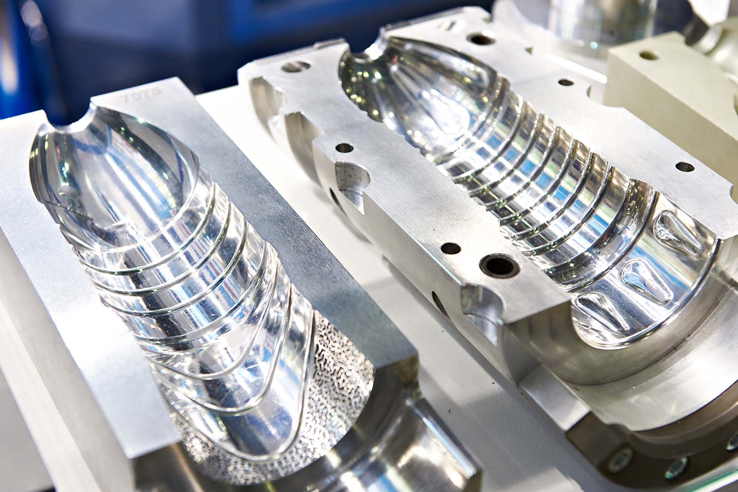
Although mold makers produce tools for many types of manufacturing processes, mold making is most often associated with tools for injection molding of plastics. There are countless parts made by injection molding. Some of the more common are food containers, storage bins, toys and automotive trim.
Injection molding is the fastest and most cost-effective way to make commodity products making it a preferred process for manufacturers. Its popularity is evident in the number of products that have been transitioned from other manufacturing processes to injection molding. If you are old, like me, you have probably complained about all the plastic parts that used to be made of metal.
Whether you think plastic parts are good or bad, they are a huge part of manufacturing, and the use of plastic will continue to increase because the parts are economical. As demand for molded parts has increased and companies seek cost reductions, competition in the mold market has increased. Therefore, sending injection molds offshore has become a prevalent practice forcing domestic mold shops to seek efficiency improvements to remain competitive.
Mold machining is characterized by long machining cycles, deep pockets, complex contours and large volumes of chips. Unlike other machining operations, increased part density, set up reduction and similar activities are not effective ways to deliver efficiency gains. Making efficiency improvements in a mold shop requires higher removal rates. Simply stated, you must make chips faster.
Machine tool builders, cutting tool makers and software developers have responded to the demand for faster removal rates in the last decades by introducing new technologies to the market. Although there is not always a clear connection to these technologies, mold machining has greatly influenced general machining technology.
High speed machining techniques are one of the most obvious advancements that have spread from mold making to general machining. High-speed machining is a catch-all term used to describe a range of techniques and technologies that have grown in popularity over the last two decades. The most common of these is the use of increased spindle speeds coupled with decreased radial depth of cut and increased axial engagement of the milling tool. Cutting tool makers frequently make use of this type of machining to demonstrate the superiority of their tools by showing a long, relatively skinny tool with full axial engagement profiling a workpiece.
These techniques were developed to improve the machining of deep pockets in molds to reduce the amount of EDM and hand finishing that was required after machining. Benefits associated with this type of machining were obvious, and quickly bled into general machine work with the aid of savvy marketing departments.
Finish machining of a mold requires using relatively small diameter tools, taking a small depth of cut and small step overs while following complex multi-axis contours. The resulting CNC programs require thousands of lines of code to execute the countless small moves needed to create the contour. Older controls often struggle to keep up and the machine will have slight hesitations between moves as it tries to process the program.
These hesitations not only impact efficiency they can cause imperfections in the finish. Machine tool controls have been improved to overcome these problems by adopting better processors that speed the internal calculations.
More importantly, control builders have increased the memory of the controls. The CNC control keeps the upcoming commands in a buffer memory so that they can be executed quickly. When you see a machine hesitate between moves it is struggling to fill the buffer memory with code. Increased memory allows more lines of code to be stored in the buffer and is usually marketed as increased “look-ahead.” Improved memory and look-ahead have benefited any shop that machines complex multi-axis contours or is controlling multiple axes simultaneously.
Creating deep pockets needed for molds can be a long arduous machining process. Traditional machining methods using milling tools induces large radial forces inviting problems like chatter. The only way to overcome the problems is to reduce the spindle speeds and take lighter cuts. To combat the problems of deep pocket roughing, cutting tool makers developed z-axis roughing. Indexable (inserted) tools were created with insert geometry specifically designed to cut in the axial direction. Pushing the tool into the part from above directs cutting forces into the stiffest part of the machine, thereby eliminating side loading of the tool. The result is a significant increase in the material removal rate.
Mold makers not only face the challenges associated with milling deep pockets, they also drill very deep holes in the molds. Drill makers have created numerous deep hole drilling tools, and today machine shops are making holes on machining centers that would have required special machines in the past.
Usually, a hole is considered deep when the depth is 10D. Once the ratio gets to 10D it is necessary to start taking precautions to ensure holes are straight and drills do not break. Special grinding techniques, through-the-tool coolant and very precise tool holders are needed to ensure these fragile drills survive. Drill makers have pushed out a tremendous number of advancements in the last few years that have made drilling to 50D possible.
Some of these advancements would have occurred independent of mold making, and one could argue that challenges in mold making were not the dominate forces driving development. Even so, the push to reduce cost and lead time of molds has positively impacted machining operations in other industrial sectors.
Related Glossary Terms
- boring
boring
Enlarging a hole that already has been drilled or cored. Generally, it is an operation of truing the previously drilled hole with a single-point, lathe-type tool. Boring is essentially internal turning, in that usually a single-point cutting tool forms the internal shape. Some tools are available with two cutting edges to balance cutting forces.
- centers
centers
Cone-shaped pins that support a workpiece by one or two ends during machining. The centers fit into holes drilled in the workpiece ends. Centers that turn with the workpiece are called “live” centers; those that do not are called “dead” centers.
- chatter
chatter
Condition of vibration involving the machine, workpiece and cutting tool. Once this condition arises, it is often self-sustaining until the problem is corrected. Chatter can be identified when lines or grooves appear at regular intervals in the workpiece. These lines or grooves are caused by the teeth of the cutter as they vibrate in and out of the workpiece and their spacing depends on the frequency of vibration.
- computer numerical control ( CNC)
computer numerical control ( CNC)
Microprocessor-based controller dedicated to a machine tool that permits the creation or modification of parts. Programmed numerical control activates the machine’s servos and spindle drives and controls the various machining operations. See DNC, direct numerical control; NC, numerical control.
- coolant
coolant
Fluid that reduces temperature buildup at the tool/workpiece interface during machining. Normally takes the form of a liquid such as soluble or chemical mixtures (semisynthetic, synthetic) but can be pressurized air or other gas. Because of water’s ability to absorb great quantities of heat, it is widely used as a coolant and vehicle for various cutting compounds, with the water-to-compound ratio varying with the machining task. See cutting fluid; semisynthetic cutting fluid; soluble-oil cutting fluid; synthetic cutting fluid.
- depth of cut
depth of cut
Distance between the bottom of the cut and the uncut surface of the workpiece, measured in a direction at right angles to the machined surface of the workpiece.
- electrical-discharge machining ( EDM)
electrical-discharge machining ( EDM)
Process that vaporizes conductive materials by controlled application of pulsed electrical current that flows between a workpiece and electrode (tool) in a dielectric fluid. Permits machining shapes to tight accuracies without the internal stresses conventional machining often generates. Useful in diemaking.
- gang cutting ( milling)
gang cutting ( milling)
Machining with several cutters mounted on a single arbor, generally for simultaneous cutting.
- grinding
grinding
Machining operation in which material is removed from the workpiece by a powered abrasive wheel, stone, belt, paste, sheet, compound, slurry, etc. Takes various forms: surface grinding (creates flat and/or squared surfaces); cylindrical grinding (for external cylindrical and tapered shapes, fillets, undercuts, etc.); centerless grinding; chamfering; thread and form grinding; tool and cutter grinding; offhand grinding; lapping and polishing (grinding with extremely fine grits to create ultrasmooth surfaces); honing; and disc grinding.
- look-ahead
look-ahead
CNC feature that evaluates many data blocks ahead of the cutting tool’s location to adjust the machining parameters to prevent gouges. This occurs when the feed rate is too high to stop the cutting tool within the required distance, resulting in an overshoot of the tool’s projected path. Ideally, look-ahead should be dynamic, varying the distance and number of program blocks based on the part profile and the desired feed rate.
- milling
milling
Machining operation in which metal or other material is removed by applying power to a rotating cutter. In vertical milling, the cutting tool is mounted vertically on the spindle. In horizontal milling, the cutting tool is mounted horizontally, either directly on the spindle or on an arbor. Horizontal milling is further broken down into conventional milling, where the cutter rotates opposite the direction of feed, or “up” into the workpiece; and climb milling, where the cutter rotates in the direction of feed, or “down” into the workpiece. Milling operations include plane or surface milling, endmilling, facemilling, angle milling, form milling and profiling.
- profiling
profiling
Machining vertical edges of workpieces having irregular contours; normally performed with an endmill in a vertical spindle on a milling machine or with a profiler, following a pattern. See mill, milling machine.
Author

Christopher Tate is the owner of Tate Engineering, a Natchez, Mississippi, firm that helps manufacturers solve efficiency problems. Tate, who earned master's degree in industrial technology from Mississippi State University, has 32 years of experience in the metalworking industry.
