 The tool and mold industry is designing and specifying ever more complex geometries and freeform surfaces and the industry is placing ever greater demands on clamping technology to accomplished these needs.
Koller Formenbau, manufacturers of prototypes and tooling and small batch and mass produced plastic parts, tackles these increasing challenges with modular zero-point clamping technology from Andreas Maier Fellbach (AMF).
"Today's molds and tools with their complex contours place significantly higher demands on clamping technology than the products of earlier years," said Markus Ferstl, head of the milling department at the Formenbau Koller GmbH in Dietfurt-Oberbürg, Germany. According to Ferstl, more features are being assimilated into the tools and thus into each assembly and module of a mold. As a result, geometries and contours are becoming increasingly complex. By the same token, the requirements of workpiece clamping technology are increasing for collision-free cutting in the production of components.
Five-sided processing
 In conjunction with five-side processing that is as automated as possible, challenges must be mastered that no one could have imagined six or seven years ago. "Thanks to the modular zero-point clamping technology from AMF, we clamp quickly and with repetition accuracy and at the same time achieve the greatest possible flexibility for largely automated five-side processing," said Paul Schaffner, who is jointly responsible for the milling department.
The automotive supplier utilizes more than 20 machines in production. In the tool-making facility at Dietfurt, 160 specialists manufacture tailor-made injection molding and composite tools as well as systems and fixtures for external customers as well as for the companies in their own group. This includes both problem-solving expertise from tool-making as well as experience from the series production of parts.
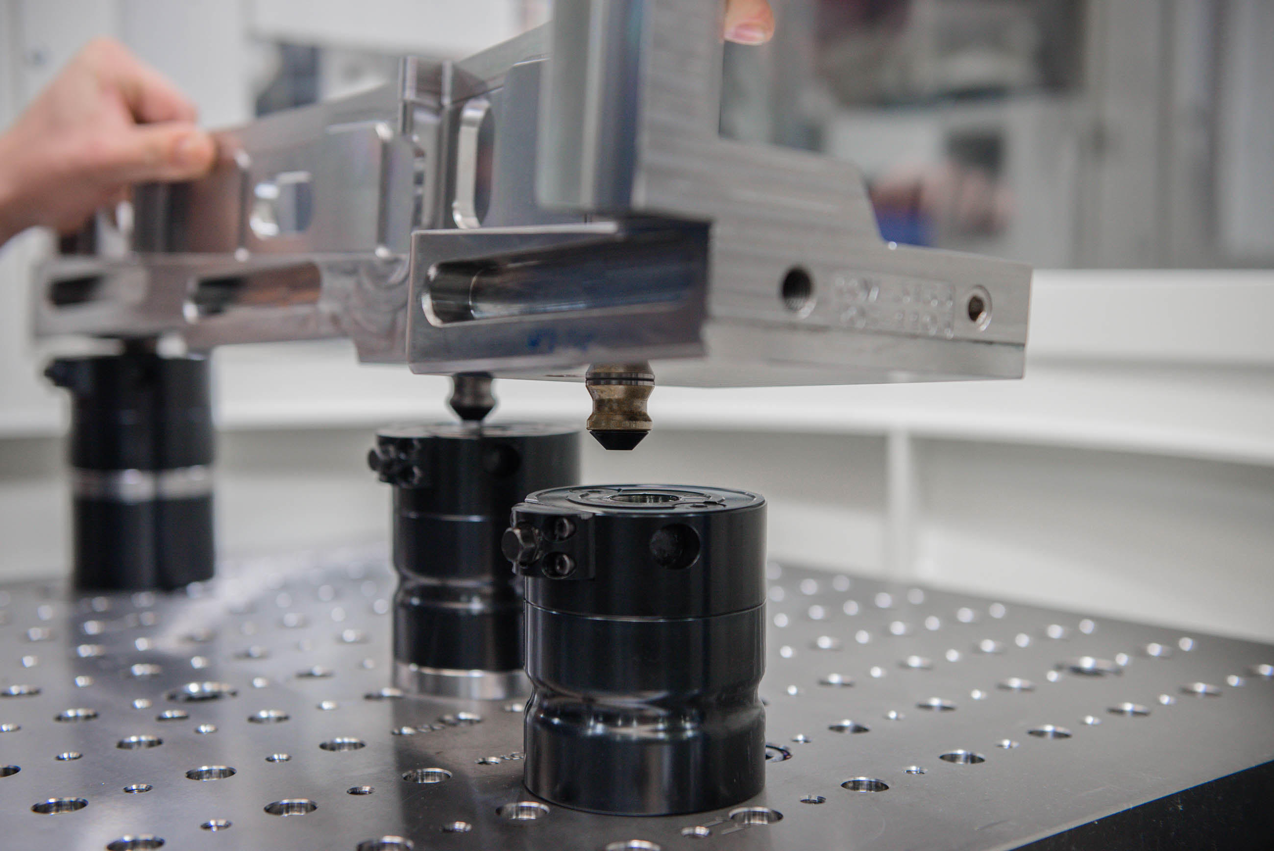
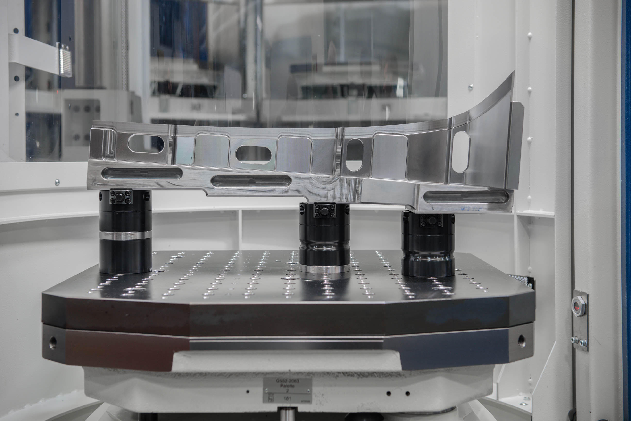
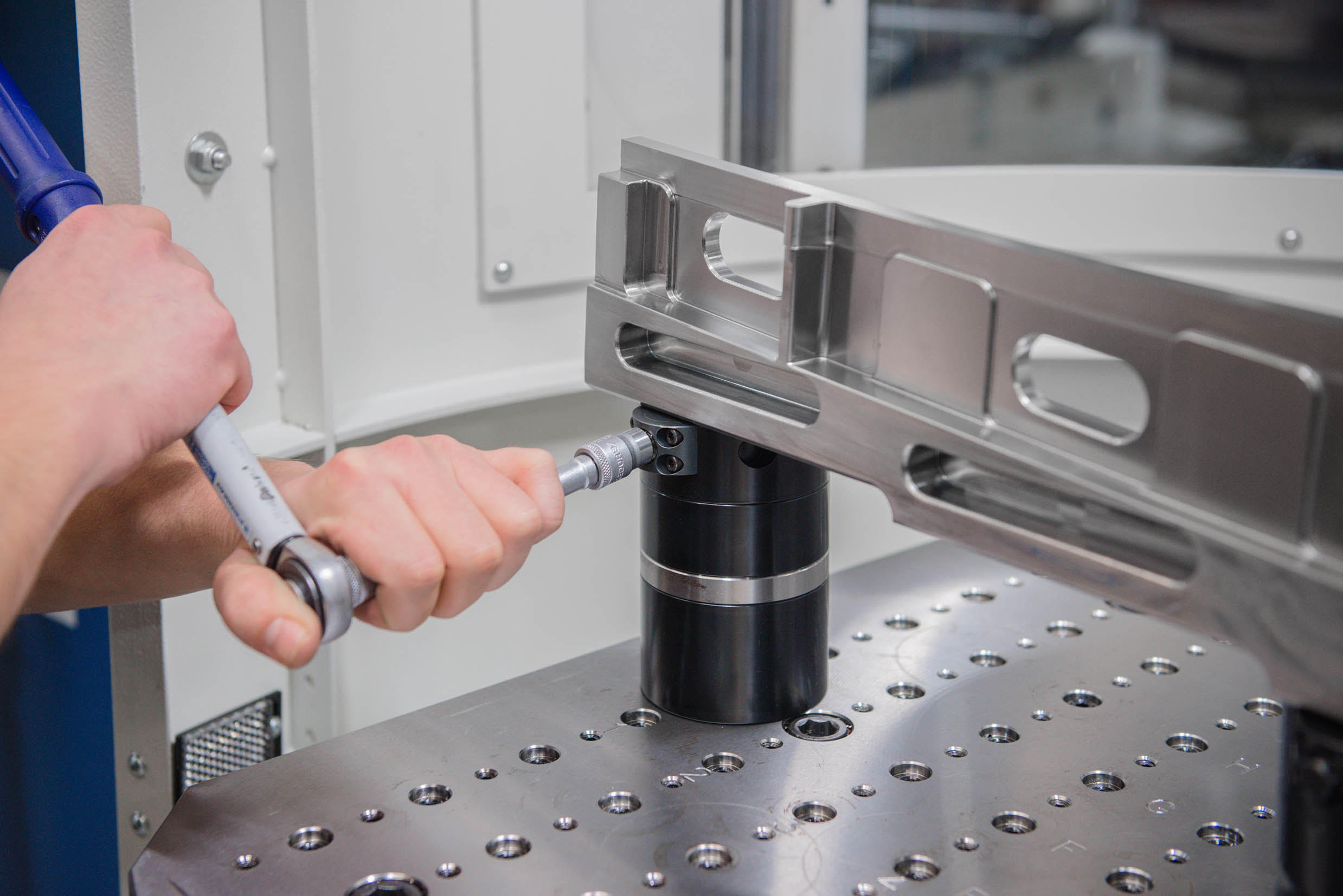
Modular zero-point clamping systems from AMF's extensive standard portfolio are used on almost all of the 22 machines. This includes clamping pallets in the dimensions 630mm x 630mm with 214 positioning holes M8 with 15mm adjustment as well as mechanical assembly clamping modules K10 as single and double modules. The clamping module has high retracting, locking and holding forces. It is opened and locked mechanically. The two companies have cooperated closely on grid plates. AMF supplied some of the plates as well as the drawings for one machine and Koller manufactured the clamping plates itself.
Avoiding collisons
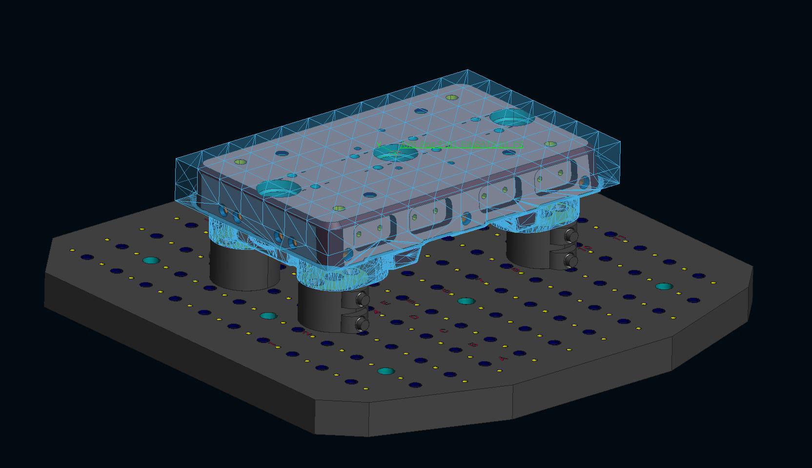
 Utilizing 3D modeling software, the company visualized potential collisions on its machines. For instance, a 5-axis machining center from Grob is equipped with a circular automated pallet changer with 13 pallets, and the workpieces are clamped directly on the pallets. Pull-studs with engagement screws in the hardened bushings of the clamping pallets hold the pull-studs of the structural and spacer elements. They are available from 20mm to 100mm. With the defined grid pitch, each pallet offers the flexibility for positioning the elements. Then, a zero-point clamping module K10 is positioned at the top, which pulls in and locks the M8 or M10 pull-studs screwed into the workpiece with 10 kN and holds it with 25 kN force. For direct clamping, the holes necessary for the pull-studs are made directly in the unmachined part.
The visualization in the 3D model is indispensable aid, said Schaffner. "In this way,“ he said, “we can identify any interfering contours for the necessary five-side processing at an early stage, and our designers plan the bushings in such a way that there is no risk of collision."
Other processes and machines
 The zero point clamping technology is used in other ways at Koller. For instance, components made of different materials are often first roughed and then mostly hardened. After finishing and other processes, such as drilling or threading, it is often necessary to erode as well. “During all of these process steps, the zero-point clamping technology from AMF brings us significant timesaving benefits, since we also incorporate the zero point that was measured once in all other machines and processes. Thus, with AMF technology we have drastically reduced set-up times and increased machine running times from 80 to 140 hours," said Schaffner. "With appropriate planning, we can also manufacture on weekends with minimal manpower.“
Apart from saving time, there is another benefit, said Christian Vogel, a sales engineer at AMF. “If workpieces are clamped with our zero-point clamping technology, there are fewer vibrations during machining. This leads to a better surface quality, which shortens process times or sometimes makes subsequent processes superfluous.“
Contact Details
Related Glossary Terms
- gang cutting ( milling)
gang cutting ( milling)
Machining with several cutters mounted on a single arbor, generally for simultaneous cutting.
- machining center
machining center
CNC machine tool capable of drilling, reaming, tapping, milling and boring. Normally comes with an automatic toolchanger. See automatic toolchanger.
- milling
milling
Machining operation in which metal or other material is removed by applying power to a rotating cutter. In vertical milling, the cutting tool is mounted vertically on the spindle. In horizontal milling, the cutting tool is mounted horizontally, either directly on the spindle or on an arbor. Horizontal milling is further broken down into conventional milling, where the cutter rotates opposite the direction of feed, or “up” into the workpiece; and climb milling, where the cutter rotates in the direction of feed, or “down” into the workpiece. Milling operations include plane or surface milling, endmilling, facemilling, angle milling, form milling and profiling.
- pitch
pitch
1. On a saw blade, the number of teeth per inch. 2. In threading, the number of threads per inch.
- threading
threading
Process of both external (e.g., thread milling) and internal (e.g., tapping, thread milling) cutting, turning and rolling of threads into particular material. Standardized specifications are available to determine the desired results of the threading process. Numerous thread-series designations are written for specific applications. Threading often is performed on a lathe. Specifications such as thread height are critical in determining the strength of the threads. The material used is taken into consideration in determining the expected results of any particular application for that threaded piece. In external threading, a calculated depth is required as well as a particular angle to the cut. To perform internal threading, the exact diameter to bore the hole is critical before threading. The threads are distinguished from one another by the amount of tolerance and/or allowance that is specified. See turning.
