Toolholder manufacturer Nikken Kosakusho Works Ltd. in Osaka, Japan, relies on accurate measurements and comprehensive cutting force data from a Kistler dynamometer to advance its solutions for demanding machining applications, both in Japan and Europe. (Kistler Group is headquartered in Winterthur, Switzerland, and Kistler Instrument Corp. is in Amherst, New York.)
In addition to high-performance toolholders, Nikken manufactures CNC rotary tables, reamers and a range of other tooling products for high-level machining applications. Since its founding in 1958, the manufacturer has expanded to over 750 employees across more than 16 countries worldwide. Nikken supplies customers in industries such as aerospace, healthcare, motorsport, power engineering, energy, molding and die casting. (Lyndex-Nikken Inc. is in Mundelein, Illinois.)
In 2014, the toolholder specialist opened the Nikken Innovation Centre Europe (NICe) at Rotherham in the U.K. This flagship facility is equipped with eight advanced machining centers for full-scale R&D work on machining applications.
“That was also when we started working with Kistler measurement technology, and we’ve continued to do so successfully ever since then,” said Susumu Mikado, senior managing director at Nikken. “The objectives in R&D are to correlate all data on cutting forces X, Y and Z with parameters such as the velocity command and torque command of the 3-axis servo motor, the spindle torque, and the accuracy and stability of the cutting surface, and to comprehensively evaluate this data. The Kistler system enabled us to accurately measure all the cutting forces needed for a new series of toolholders, and also to compare the process performance for all the toolholders.”
Nikken developed the products in its X-Treme Chuck series for demanding aerospace and energy applications. They provide high repeatable accuracy and excellent runout characteristics while preventing endmill movement, or “pulling- out,” according to the company.
Nikken relied on the 9255C dynamometer from Kistler. With its portfolio of piezoelectric dynamometers, Kistler can provide solutions for multiple machining applications, including milling, drilling, turning and grinding, from micromachining to heavy-duty cutting. Dynamometers from Kistler are reportedly used in many R&D applications, and they also play a key part in optimizing production processes.
Thanks to its rigidity and natural frequency, this piezoelectric sensor array (comprising four 3-axis force sensors) used by Nikken measures enables precise measurement of cutting forces and moments in the three orthogonal axes. Another benefit of the 9255C dynamometer is its high resolution, allowing it to capture fine dynamic changes — even in the presence of large forces. Features such as a wide measuring range (Fx, Fy: ±30 kN and Fz: -10 to 60 kN), ground-isolation sensor integration and protection class IP67 make the 9255C suitable for heavy-duty applications in R&D and production.
“Thanks to Kistler’s help, we were able to standardize our process and method for the original workpiece, which measured 150 mm × 150 mm × 100 mm (5.9" × 5.9" × 3.9"). Our product was originally developed to manufacture jet engine components made of a special titanium alloy. The dynamometer’s great performance, ease of use and data quality, backed up by excellent service from Kistler were major factors in the success of our project,” Mikado said.
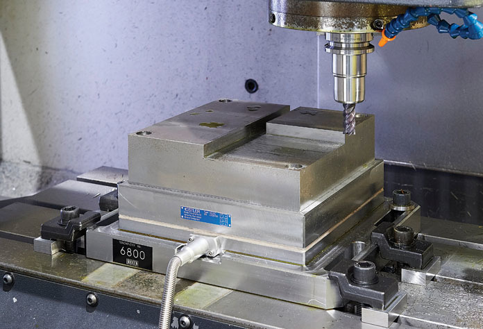
The 9255C dynamometer from Kistler is a multiple-component force sensor for robust and precise dynamic measurements in demanding applications. Kistler Group
In 2020, Nikken reports that it opened a new technical center at its headquarters in Japan, equipped with the latest machining technologies to achieve the highest possible accuracy.
“In view of that, we moved the Kistler dynamometer to our new center. Since then, the 9255C has delivered an enormous volume of cutting data on different types of shanks and chucks, not only for basic evaluation, but also to support the specification of material characteristics,” Mikado said.
R&D efforts at the new technical center in Osaka resulted in the development of a dynamic double- face-contact tooling system. This Nikken innovation is at the core of a new toolholder series with many different variants, including the dynamic 2Lock tooling system (BT double face contact).
“The Kistler dynamometer has helped us to continue developing our solutions and has even paved the way for some real innovations,” Mikado explained. “The technical support we receive from Kistler Japan is also very good, not only for commissioning and basic knowledge exchange, but also when it comes to optimizing the measuring chain and the entire R&D system, including aspects such as interfaces and data processing.”
Contact Details

Contact Details
Related Glossary Terms
- centers
centers
Cone-shaped pins that support a workpiece by one or two ends during machining. The centers fit into holes drilled in the workpiece ends. Centers that turn with the workpiece are called “live” centers; those that do not are called “dead” centers.
- chuck
chuck
Workholding device that affixes to a mill, lathe or drill-press spindle. It holds a tool or workpiece by one end, allowing it to be rotated. May also be fitted to the machine table to hold a workpiece. Two or more adjustable jaws actually hold the tool or part. May be actuated manually, pneumatically, hydraulically or electrically. See collet.
- computer numerical control ( CNC)
computer numerical control ( CNC)
Microprocessor-based controller dedicated to a machine tool that permits the creation or modification of parts. Programmed numerical control activates the machine’s servos and spindle drives and controls the various machining operations. See DNC, direct numerical control; NC, numerical control.
- cutting force
cutting force
Engagement of a tool’s cutting edge with a workpiece generates a cutting force. Such a cutting force combines tangential, feed and radial forces, which can be measured by a dynamometer. Of the three cutting force components, tangential force is the greatest. Tangential force generates torque and accounts for more than 95 percent of the machining power. See dynamometer.
- die casting
die casting
Casting process wherein molten metal is forced under high pressure into the cavity of a metal mold.
- dynamometer
dynamometer
When drilling, a device for measuring the generated torque and axial force (thrust). When milling, a device for measuring the generated torque and feed force. When turning, a device for measuring the tangential, feed and radial forces.
- endmill
endmill
Milling cutter held by its shank that cuts on its periphery and, if so configured, on its free end. Takes a variety of shapes (single- and double-end, roughing, ballnose and cup-end) and sizes (stub, medium, long and extra-long). Also comes with differing numbers of flutes.
- gang cutting ( milling)
gang cutting ( milling)
Machining with several cutters mounted on a single arbor, generally for simultaneous cutting.
- grinding
grinding
Machining operation in which material is removed from the workpiece by a powered abrasive wheel, stone, belt, paste, sheet, compound, slurry, etc. Takes various forms: surface grinding (creates flat and/or squared surfaces); cylindrical grinding (for external cylindrical and tapered shapes, fillets, undercuts, etc.); centerless grinding; chamfering; thread and form grinding; tool and cutter grinding; offhand grinding; lapping and polishing (grinding with extremely fine grits to create ultrasmooth surfaces); honing; and disc grinding.
- milling
milling
Machining operation in which metal or other material is removed by applying power to a rotating cutter. In vertical milling, the cutting tool is mounted vertically on the spindle. In horizontal milling, the cutting tool is mounted horizontally, either directly on the spindle or on an arbor. Horizontal milling is further broken down into conventional milling, where the cutter rotates opposite the direction of feed, or “up” into the workpiece; and climb milling, where the cutter rotates in the direction of feed, or “down” into the workpiece. Milling operations include plane or surface milling, endmilling, facemilling, angle milling, form milling and profiling.
- toolholder
toolholder
Secures a cutting tool during a machining operation. Basic types include block, cartridge, chuck, collet, fixed, modular, quick-change and rotating.
- turning
turning
Workpiece is held in a chuck, mounted on a face plate or secured between centers and rotated while a cutting tool, normally a single-point tool, is fed into it along its periphery or across its end or face. Takes the form of straight turning (cutting along the periphery of the workpiece); taper turning (creating a taper); step turning (turning different-size diameters on the same work); chamfering (beveling an edge or shoulder); facing (cutting on an end); turning threads (usually external but can be internal); roughing (high-volume metal removal); and finishing (final light cuts). Performed on lathes, turning centers, chucking machines, automatic screw machines and similar machines.
Author
News items authored by Cutting Tool Engineering have been written or edited by the editors of Cutting Tool Engineering magazine. The reports represent material submitted to CTE by outside authors, and edited by CTE editors for style and accuracy.