Gidelines for using twin-cutter boring heads.
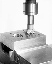
The twin-cutter boring head is an internal tool that incorporates two inserts and typically is used for rough boring. It’s capable of holding bore tolerances of about 0.002".
Cutting force equilibrium is established by the two opposing inserts returning a balanced force to the centerline of the spindle, the most rigid part of the machine tool. This balanced force is one of the major strengths of the twin cutter, because it allows the tool to accurately bore holes that lack positional accuracy, straightness and/or roundness.
A properly engineered twin cutter must, above all else, have high stability and rigidity to withstand the heavy cutting conditions encountered in rough boring (Figure 1). Good twin-cutter boring tools also have the following features or capabilities:
- Replaceable-insert holders that seat the largest, ISO-standard, positive-geometry inserts available. In order for the twin cutter to perform a variety of rough-boring operations, the toolmaker should—at a minimum—offer holders that can accommodate CCMT, SCMT or WCMX inserts.
- For maximum versatility, the work ranges of individual twin cutters should overlap with the work ranges of the other tools offered.
- Through-coolant capability.
- Allow radial and axial adjustments to be made for each insert. Being able to adjust insert height is very important because it permits stepped cutting (discussed below) and ensures proper chip control when cutting materials that produce long chips.
- Solid locking system with large clamping screws that won’t interfere with chip evacuation. The assembled tool must be highly resistant to vibration, and it needs to withstand high torsional stresses and the violent forces encountered during interrupted cutting.
- Modular design that allows the system to bore all sizes and depths of holes and be used with all types of machine spindles and equipment.
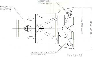
Figure 1: The features of a good twin cutter include independently adjustable inserts, a modular connection, a wide work range and the ability to accept large, positive inserts.
Rough-boring tools that meet the above criteria will semifinish holes to the required geometric form (roundness) and positional accuracy, under the most severe cutting conditions, and will minimize the number of tools needed.
Methods of Rough Boring
There are three primary ways to rough-bore with a twin-cutter head: balanced cutting, stepped cutting and full-profile cutting (Figure 2). The method chosen is determined by factors such as part configuration, initial stock allowance, production requirements, equipment limitations and part-quality considerations.
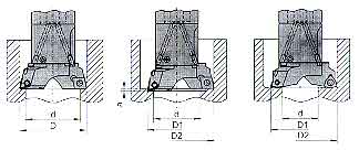
Figure 2: There are three common methods for rough boring with a twin-cutter head: balanced (left), stepped (center) and full profile.
The main determinants are the workpiece material, stock allowance and the width of the insert cutting edge. Users should consult the insert manufacturer for the recommended maximum depth of cut, but, generally, the following rules apply:
|
Balanced is the most common type of twin-cutter boring. It can be performed at higher feed rates than the other two methods and offers the highest tool stability. Semifinished-bore quality is optimized, yielding the best bore location, size, roundness and repeatability. The key to ensuring success when utilizing this roughing method is to preset, as near as possible, the axial heights of both inserts. This is especially important for extreme bore depths and long-chipping materials, like low-carbon steel. Unequal insert heights will generate unequal feed rates, resulting in higher cutting forces being directed to one side of the bore.
For example, if there were a 0.001" axial height difference between two inserts, a feed displacement of 0.002 ipr would result. So if the tool were feeding at 0.010 ipr, the respective feeds would be 0.004" and 0.006", which could cause chip control problems.
Users can select any lead angle and insert for balanced cutting, but square inserts with a 6° positive lead are the most popular for through-holes when breakout or burr rollover have to be closely controlled.
The stepped-cutting method is primarily for workpieces with large stock allowances or excessive core shifts—the amount the centerline of the cored hole deviates from the centerline of the finished bore. It also can be used in applications that require a smaller DOC in order to ensure proper chip control, as would be the case with parts made of low-carbon steel or stainless steel.
The tool is preset so that each insert cuts half of the original stock allowance. The inserts are set up to machine two different diameters that are axially spaced 0.008" apart. Because the tool is now considered to have only one effective insert instead of two, as in balanced cutting, the feed rate must be reduced accordingly.
Only inserts that have a 0° lead angle should be used for this method of roughing, because much larger axial differences are required when applying inserts with either positive or negative lead angles.
Full-profile cutting, which should only be done with WCMX-type inserts, facilitates the removal of large stock allowances in a single pass. The unique shape of the insert allows for different diameter settings without the need for any height adjustment.
The inserts can be arranged to create four independent profiles, at a light feed, and still maintain chip control. Caution must be exercised, however, as large amounts of chips are produced; they must be cleared away to prevent them from being recut.
Additionally, insert holders can be set with different lead angles. This allows twin cutters to perform chamfering tasks. Front and back chamfering can be done by either plunging or circular interpolation (Figure 3).
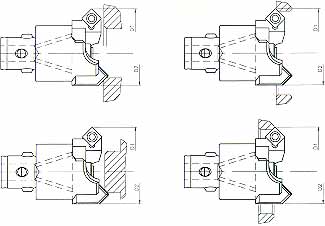
Figure 3: Twin-cutter insert holders can be used for chamfering. Front and back chamfering is accomplished by either plunging or circular interpolation.
The stepped-cutting method is primarily for workpieces with large stock allowances or excessive core shifts, which is the amount the centerline of the cored hole deviates from the centerline of the finished bore.
Comparing Alternatives
As with any tool, twin cutters won’t be the best solution for every job. For example, vertical applications with large stock allowances and blind bores with no place for chips to evacuate prove problematic for twin cutters. Nevertheless, most holes can be efficiently rough-bored with a twin cutter.
That’s not the case when using a single-cutter finish-boring tool for roughing-especially one used to open a cored hole (see accompanying article). The finisher’s inserts are too small, and the tool lacks the heavy-duty construction rough boring demands.
More importantly, finishing tools lack cutting-force balance, prohibiting them from correcting bore location without making three, or even four, passes per hole. Also, it is typical for finish-boring tools to be equipped with triangular inserts. Using them in heavy cuts can accelerate the loss of insert-pocket integrity and, therefore, lead to a loss of repeatability during subsequent precision-finish-boring operations.
An advantage of circular milling is that the tool can perform many operations. If the rough-bore is quite short and accessible to the spindle, efficient roughing can be accomplished. However, if the bore depth is such that 3-axis interpolation and two or more paths are needed to generate size, considerable milling time will be required.
When bore depth exceeds one or two times the length-to-diameter ratio, feed rates for the milling tool must be reduced—a result of the radial cutting forces stemming from tool overhang. Consequently, circumferential clamping of the workpiece will be necessary to ensure that the milling operation is vibration-free and no out-of-round bores are produced.
Over an extended production period, circular milling will also place undo wear on the machine’s spindle bearings and insert consumption will be much higher than with a twin cutter.
Most of the time when choosing between roughing with a circular-milling tool and a twin cutter, doing some quick speed-and-feed calculations will give the user a good estimate of the time per hole each method will consume. It then will be fairly simple to determine which approach is more cost-effective.
Twin-Cutter Guidelines
As mentioned earlier, the maximum stock allowance a twin cutter can handle is based on the size of the tool’s inserts and the workpiece material. However, certain conditions, such as material hardness or bore depth, may take precedence. If either happens, the maximum stock allowance the twin cutter can handle will decrease.
Two keys to successful rough boring with twin cutters are to always cut short, “6”-shaped chips and ensure chips are properly evacuated.
If the available machine power is insufficient to drive the tool without stalling the spindle, reducing the feed rate may result in long, stringy chips. These tend to clog the bore and wrap around the tool. If this situation arises, check the torque curve of the machine (found in the machine’s manual) and make the appropriate spindle-speed adjustment to increase available power. This condition usually presents itself when boring larger diameters (4" and larger), which require a lower rpm.
| L/D Ratio | Speed and Stock Allowance Reduction | Insert Radius |
| <4:1 | 100% of recommendation | 0.016"-0.031" |
| 5:1 | 75% of recommendation | 0.016" |
| 6:1 | 60% of recommendation | 0.008"-0.016" |
| 7:1+ | 50% of recommendation* | 0.008" |
| *Inquire about using carbide or heavy-metal bars to reduce chatter. | ||
Another factor that will affect rough boring is tool length. For each increase in the length-to-diameter ratio above 4:1, reduce, by drilling, the stock allowance by 10 to 15 percent to reduce cutting forces and maintain vibration-free boring. When rough boring to extreme depths, select an insert that has a smaller nose radius, especially if the stock allowance is not heavy (see chart).
Insert size and geometry will determine the minimum/maximum feed rates needed to obtain ideal chip formation. When chip thickness or radial DOC exceeds more than 40 percent of the insert’s cutting edge width, it will be necessary to increase the feed 10 to 20 percent in order to break the chips.
The finishing tool lacks cutting-force balance, prohibiting it from correcting the bore location in one pass.
Before exceeding the insert manufacturer’s maximum feed rate, though, it will usually help to change the tool to the stepped-cutting arrangement to reduce chip thickness and the required feed rate. When using the stepped method, the maximum feed should never exceed two times the difference in axial height between the two inserts. In other words, an 0.008" lead will allow for a maximum feed of 0.015 ipr.
Consult the insert manufacturer’s recommended surface footage for the material to be bored. Extended tool length will require a reduction in speed to reduce the incidence of chatter or vibration.
|
|||||||||||||||||||||
Recent advances in silicon-nitride inserts have greatly increased operating speeds and tool life in the rough boring of grey cast iron (see chart below). Because of the high cutting speeds involved, use only inserts that have center holes and Torx screws for clamping. These features will help ensure that the inserts won’t be thrown from the tool due to centrifugal forces. At elevated speeds, centrifugal force can be high enough to throw inserts secured by top-clamp systems.
The flexibility and production improvements provided by the twin cutter can greatly increase product manufacturing. Hole quality improves, positional accuracy is maintained and machine wear—due to either unequal loading from single-cutter boring tools or from circular milling—is kept to an absolute minimum.
Applications for twin-cutter boring tools
Twin-cutter boring tools are considered essential for certain types of jobs. Among them are applications involving castings and forgings. By design, most of the holes in these parts are cast in place. Known as “cored holes,” they’re created by placing a tapered leader pin into the mold cavity (see illustration). The result is an undersized hole that is bored later, during the machining process. Boring cored holes is difficult because of the large amount of stock that’s removed and the need to remove material so as to correct the bore position.
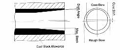
A cored hole (left) is created by placing a tapered leader pin into the mold cavity. An advantage of the twin cutter is that it can adjust for any core shifting, correcting the bore position.
When a cored hole is relocated by boring, the stock allowance is greater on one side than the other. As a result, an uneven radial cutting force is imparted to the boring tool. And as the roughing tool feeds deeper into the hole, the stock allowance increases on each side, due to the draft angle made by the tapered leader pin. The twin-cutter balances the uneven radial forces applied to the tool and can take off more material per pass, reducing the cycle time of the rough-boring operation.
Weldments also are high on the “applications list” of twin-cutter boring heads. Holes that are greater than 4" in diameter are normally “burned-in” during the fabrication process, or bosses are turned, drilled and then welded into place. These types of workpieces present the same location and stock-removal problems as cored holes, along with the added difficulty of chip control.
Weldments are made from low-carbon steel, such as 1010 or A-36. These materials form difficult-to-break chips. The hardened crust that results from the burnout operation, and the slight air gaps between the welded components, increases the difficulty of the boring operation. Weldments also tend to have large, complex shapes that are difficult to fixture and require extreme length-to-diameter boring tools. Twin-cutter boring tools can accommodate the larger hole sizes and provide more rigid cutting when a longer reach is required.
Another popular job for twin cutters is enlarging undersized holes. This is typical of workpieces that need to be produced on smaller machines, with low spindle torque, that call for holes larger than 11¼2" in diameter. Machinists usually try to drill the largest hole the machine can handle, then use a twin cutter to bore the hole to the desired diameter. This lets larger holes be processed during the same setup, increasing a low-powered machining center’s versatility.
Mold bases often are overlooked as an application for twin cutters. The guidepost holes are drilled first. But drilling compromises hole straightness because of the extreme hole depths. This can be problematic, since these holes are close to the wall of the mold. Therefore, many shops use a series of single-cutter boring tools to improve the location and hole straightness. But by employing a rigid twin cutter, machinists can create the final hole size and correct for straightness and location in a single pass.
Additional uses for the twin cutter include semifinish boring of tight-tolerance bores, aluminum die castings and counterboring operations. Twin cutters that use insert holders also can be used for chamfering, boring and facing operations with a lathe, and OD turning operations on a milling center.-J. Burley
About the Author
Jack Burley is national product manager of rotating tools for KPT Kaiser Precision Tooling Inc., Elk Grove Village, Ill
Related Glossary Terms
- alloys
alloys
Substances having metallic properties and being composed of two or more chemical elements of which at least one is a metal.
- aluminum alloys
aluminum alloys
Aluminum containing specified quantities of alloying elements added to obtain the necessary mechanical and physical properties. Aluminum alloys are divided into two categories: wrought compositions and casting compositions. Some compositions may contain up to 10 alloying elements, but only one or two are the main alloying elements, such as copper, manganese, silicon, magnesium, zinc or tin.
- boring
boring
Enlarging a hole that already has been drilled or cored. Generally, it is an operation of truing the previously drilled hole with a single-point, lathe-type tool. Boring is essentially internal turning, in that usually a single-point cutting tool forms the internal shape. Some tools are available with two cutting edges to balance cutting forces.
- boring head
boring head
Single- or multiple-point precision tool used to bring an existing hole within dimensional tolerance. The head attaches to a standard toolholder and a mechanism permits fine adjustments to be made to the head within a diameter range.
- burr
burr
Stringy portions of material formed on workpiece edges during machining. Often sharp. Can be removed with hand files, abrasive wheels or belts, wire wheels, abrasive-fiber brushes, waterjet equipment or other methods.
- chamfering
chamfering
Machining a bevel on a workpiece or tool; improves a tool’s entrance into the cut.
- chatter
chatter
Condition of vibration involving the machine, workpiece and cutting tool. Once this condition arises, it is often self-sustaining until the problem is corrected. Chatter can be identified when lines or grooves appear at regular intervals in the workpiece. These lines or grooves are caused by the teeth of the cutter as they vibrate in and out of the workpiece and their spacing depends on the frequency of vibration.
- counterboring
counterboring
Enlarging one end of a drilled hole. The enlarged hole, which is concentric with the original hole, is flat on the bottom. Counterboring is used primarily to set bolt heads and nuts below the workpiece surface.
- cutting force
cutting force
Engagement of a tool’s cutting edge with a workpiece generates a cutting force. Such a cutting force combines tangential, feed and radial forces, which can be measured by a dynamometer. Of the three cutting force components, tangential force is the greatest. Tangential force generates torque and accounts for more than 95 percent of the machining power. See dynamometer.
- depth of cut
depth of cut
Distance between the bottom of the cut and the uncut surface of the workpiece, measured in a direction at right angles to the machined surface of the workpiece.
- feed
feed
Rate of change of position of the tool as a whole, relative to the workpiece while cutting.
- finishing tool
finishing tool
Tool, belt, wheel or other cutting implement that completes the final, precision machining step/cut on a workpiece. Often takes the form of a grinding, honing, lapping or polishing tool. See roughing cutter.
- fixture
fixture
Device, often made in-house, that holds a specific workpiece. See jig; modular fixturing.
- gang cutting ( milling)
gang cutting ( milling)
Machining with several cutters mounted on a single arbor, generally for simultaneous cutting.
- hardness
hardness
Hardness is a measure of the resistance of a material to surface indentation or abrasion. There is no absolute scale for hardness. In order to express hardness quantitatively, each type of test has its own scale, which defines hardness. Indentation hardness obtained through static methods is measured by Brinell, Rockwell, Vickers and Knoop tests. Hardness without indentation is measured by a dynamic method, known as the Scleroscope test.
- interpolation
interpolation
Process of generating a sufficient number of positioning commands for the servomotors driving the machine tool so the path of the tool closely approximates the ideal path. See CNC, computer numerical control; NC, numerical control.
- lathe
lathe
Turning machine capable of sawing, milling, grinding, gear-cutting, drilling, reaming, boring, threading, facing, chamfering, grooving, knurling, spinning, parting, necking, taper-cutting, and cam- and eccentric-cutting, as well as step- and straight-turning. Comes in a variety of forms, ranging from manual to semiautomatic to fully automatic, with major types being engine lathes, turning and contouring lathes, turret lathes and numerical-control lathes. The engine lathe consists of a headstock and spindle, tailstock, bed, carriage (complete with apron) and cross slides. Features include gear- (speed) and feed-selector levers, toolpost, compound rest, lead screw and reversing lead screw, threading dial and rapid-traverse lever. Special lathe types include through-the-spindle, camshaft and crankshaft, brake drum and rotor, spinning and gun-barrel machines. Toolroom and bench lathes are used for precision work; the former for tool-and-die work and similar tasks, the latter for small workpieces (instruments, watches), normally without a power feed. Models are typically designated according to their “swing,” or the largest-diameter workpiece that can be rotated; bed length, or the distance between centers; and horsepower generated. See turning machine.
- lead angle
lead angle
Angle between the side-cutting edge and the projected side of the tool shank or holder, which leads the cutting tool into the workpiece.
- milling
milling
Machining operation in which metal or other material is removed by applying power to a rotating cutter. In vertical milling, the cutting tool is mounted vertically on the spindle. In horizontal milling, the cutting tool is mounted horizontally, either directly on the spindle or on an arbor. Horizontal milling is further broken down into conventional milling, where the cutter rotates opposite the direction of feed, or “up” into the workpiece; and climb milling, where the cutter rotates in the direction of feed, or “down” into the workpiece. Milling operations include plane or surface milling, endmilling, facemilling, angle milling, form milling and profiling.
- modular design ( modular construction)
modular design ( modular construction)
Manufacturing of a product in subassemblies that permits fast and simple replacement of defective assemblies and tailoring of the product for different purposes. See interchangeable parts.
- outer diameter ( OD)
outer diameter ( OD)
Dimension that defines the exterior diameter of a cylindrical or round part. See ID, inner diameter.
- turning
turning
Workpiece is held in a chuck, mounted on a face plate or secured between centers and rotated while a cutting tool, normally a single-point tool, is fed into it along its periphery or across its end or face. Takes the form of straight turning (cutting along the periphery of the workpiece); taper turning (creating a taper); step turning (turning different-size diameters on the same work); chamfering (beveling an edge or shoulder); facing (cutting on an end); turning threads (usually external but can be internal); roughing (high-volume metal removal); and finishing (final light cuts). Performed on lathes, turning centers, chucking machines, automatic screw machines and similar machines.