Lately, machining centers and cutting tools have been in a productivity race that has accelerated to near breakneck speed. Machine tool manufacturers have made significant improvements in the speed and accuracy of their products, while cutting tool manufacturers have worked to take advantage of them.
In the following pages, CUTTING TOOL ENGINEERING examines five key areas where toolmakers are striving to improve the metalcutting process, and we look at current research aimed at improving the process in the future.
Multifunctional Tools
Cycle time and tool life continue to be the two most pressing issues in metalcutting. Nine years ago, Mike Pollizzi, president of Hartland Cutting Tools Inc., Cary, Ill., began addressing these issues by making single tools capable of performing multiple operations. He continues to successfully decrease cycle time and increase tool life with custom tools for high-volume first-, second- and third-tier suppliers to the auto industry.
For example, General Motors Corp.’s V-8 engine plant in Flint, Mich., recently had a job that involved drilling and chamfering a hole in solid cast iron. First, a spot drill was used to create a 0.625"-dia. hole. It was followed by a 0.750" drill and a 1.375" chamfering tool. The three HSS tools used each averaged 1,500 holes.
Hartland developed a single coolant-fed, straight-flute tool to accomplish all three operations in the same feed cycle. The multipurpose tool has an uncoated, C-2 micrograin-carbide tip. At $400, it costs more than the three HSS tools it replaced. But it not only does the job faster, it produces about 5,000 holes. Now the job requires only one tool change and a lot less time is spent replacing dull tools. After resharpening, the multipurpose tool still averages more than 3,700 holes.
Multipurpose inserts have also contributed to faster throughput over the last decade.
Mike Gadzinski, national training manager at Iscar Metals Inc., Arlington, Texas, said that in the past, four or five different inserts might have been used to turn a part. Today, a single multipurpose insert can deep-groove, Z-axis turn, face or ID-groove and ID-bore. While each operation requires a different speed and feed rate, and possibly another holder, this is addressed in the part program. The result is less wasted chip-to-chip tool-change time, more pockets available in the turret for redundant tooling and less downtime spent replacing or indexing inserts.
Geometry
The geometry of carbide tools has changed dramatically to meet users’ demands for speed, according to Ken Bidstrup, applications specialist at Sanders Tools & Supplies Inc., Itasca, Ill. Geometry is critical to machining performance. In fact, Bidstrup asserts that 70 percent of a cutting tool’s performance is based on geometry and 30 percent on coating or substrate.
Ten years ago, Bidstrup said, inserts with a double-negative rake angle were used to mill most cast irons. Inserts with a positive-radial/negative-axial rake angle were used to cut most steels and some high-temperature alloys. A double-positive geometry was the accepted design for the light machining and finishing of most materials.
Today, most milling inserts have a negative-radial/positive-axial rake angle, which is the opposite from tools of years past. Why the change? Bidstrup explained that customers today are making lighter, higher-speed cuts on a wider variety of materials.
For example, the older positive-radial/negative-axial geometry used for inserts in a 4" facemill would typically call for a 0.200" depth of cut at 300 to 400 sfm. The finishing pass, made with an insert having a double-positive geometry, would be done at a 0.050" DOC at 600 sfm. Today’s negative- radial/positive-axial design will rough at only 0.120" to 0.150" DOC, but the speed will be in the range of 700 to 800 sfm. The same geometry then makes a lighter finish pass of 0.010" to 0.015" at 1,200 to 1,500 sfm.
Materials
Today, almost half of the cutting tools used worldwide are made of carbide (Table 1).
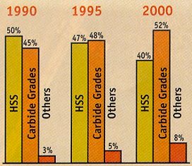
Table 1: Estimated worldwide consumption of cutting tools, by material.
“Ten years ago, nobody ever asked me what percentage of cobalt was in my carbide or what grade I used,” said Pollizzi. “While there were C-1 to C-13 grades back then, most carbide tools were made with C-2 or C-2 micrograin. Customers simply did not ask; they just wanted a carbide tool.”
Today, new grades of carbide continue to be developed within the traditional C family. Gadzinski said submicron grades retain the hardness of traditional carbide but are as tough as HSS. These submicron grades have a denser grain structure, with a transverse rupture strength approaching that of M-2 or M-4 HSS. This can be especially helpful in drilling, Gadzinski noted.
Coatings
New developments in coatings have also significantly improved tool performance. Bidstrup said that the most common coating he encounters today is aluminum oxide. About 35 percent of the milling inserts sold by his company are coated with Al2O3, while HSS and carbide drills and endmills tend to be coated with titanium nitride.
Gadzinski agreed with Bidstrup’s assessment of current coating trends, but he believes that a change is occurring. He sees rapid growth in the use of titanium-carbonitride coatings applied by the physical vapor deposition process. These versatile coatings can be used for the machining of most irons and steels, including stainless and some high-temperature alloys.
Iscar’s IC328, for example, is a TiCN-coated carbide grade designed for the general milling of most steel alloys and stainless steels at speeds up to 600 sfm. According to Gadzinski, the TiCN coating for this grade is one of the toughest, most wear-resistant coatings on the market today. The coating’s drawback, he said, is that its wear characteristics begin to fade above 600 sfm.
For high-speed machining applications, Gadzinski sees continued growth in titanium-aluminum-nitride coatings, which are often described as the next generation of Al2O3 coatings. Popular coatings, such as TiN, become more thermally conductive when heated, hastening tool breakdown. TiAlN, on the other hand, does just the opposite by producing a heat barrier between the cutting area and the substrate.
As heat rises during machining, Gadzinski explained, TiAlN chemically reacts, creating a layer of Al2O3. This reduces thermal conductivity between the cutting area and the tool. The hotter the cutting area becomes, the less thermally conductive the TiAlN-coated tool becomes.
While TiAlN is typically used to coat endmills and inserts, Hartland has begun coating drills with TiCN and a combination TiCN/TiAlN coating called Futura, which is produced by Balzers Tool Coating Inc., North Tonawanda, N.Y.
Hartland used Futura to coat live tools for a drilling operation on a multitask CNC lathe at Mennies Machine Co., Granville, Ill. Mennies was attempting to drill perpendicular to an outer diameter. TiN-coated, C-2 carbide drills were achieving about 1,000 holes per tool. Using a Hartland C-5 carbide drill coated with Futura, Mennies extended tool life to 3,000 holes.
Coolant Delivery
There seems to be widespread support for through-coolant systems among tool users. However, there are still a lot of machines in the field that can’t deliver coolant through the spindle to the cutting edge. In fact, this feature is still a factory-installed option on many machines.
Through-coolant capability is essential to increasing machining productivity, and market demand is growing. Bidstrup noted that customers who bought machines five years ago are now buying new machines with traditional (70 to 300 psi) or high-pressure (above 1,000 psi) through-coolant systems.
Through-coolant specifications depend on the pressures that the machine can handle. Special spindles are required for high-pressure applications. Also, in high-speed situations, centrifugal force can limit how much coolant gets to the tool tip, which reduces effectiveness. The solution may be high-pressure systems, which are being offered by an increasing number of manufacturers and third-party vendors.
As an alternative to purchasing a high-pressure, through-coolant system, some end users opt to retrofit their machines with an inducer to accommodate through-coolant tools. Inducers cost anywhere from $900 to $1,500 and connect between the spindle and the toolholder.
However, Bidstrup is reluctant to apply them except as a last resort, because an inducer can extend the tool an additional 6" away from the spindle, which reduces rigidity. Additionally, the speed inducers can be operated at is generally limited to 5,000 to 6,000 rpm, so they are not a solution for high-speed machining applications.
On the Horizon
Following are three areas that will be generating a lot of interest among tool users in the coming years.
Balancing. As speed and feed rates increase, tool balancing becomes a critical issue. Kennametal Inc., Latrobe, Pa., introduced a new balancing system in May that reportedly allows tools to be balanced dynamically in the machine spindle. Mark Huston, Kennametal’s director of global standard-product engineering, reported that this system adjusts for errors in the holder, tool and machine spindle and minimizes tool tip displacement.
In Kennametal’s automatic balancing system, magnetic balancing rotors embedded in a toolholder rotate to a virtually infinite number of positions around the centerline of the holder. The holder is placed in the spindle with the tool and lowered into an electromagnetic coil only about 5" to 6" in diameter. As the rpm is ramped up to the desired speed, the coil electromagnetically rotates the balancing rotors in the holder. Kennametal says that this process takes less than two seconds.
The magnetic rotors are reportedly strong enough to withstand high spindle speeds without moving. Huston said the system can maintain tool displacement to less than 0.5µm at the tool tip, and it takes into account the cumulative errors generated in the machine spindle. A complete system, including the hardware, software and six holders, carries a price tag just under $20,000.
Kennametal recently introduced an automatic balancing system that reportedly allows tools to be balanced dynamically in the machine spindle.
‘Supersonic’ speeds. Once this kind of balance is achieved, tools can be run at faster speeds. Huston said Kennametal is currently testing a new “supersonic” cutter body that reached speeds of Mach 2.6 before failing. In a recent test, a 12" cutter body reached a maximum speed of 173,000 sfm. Kennametal estimates a safe running speed of 78,500 sfm for this particular design.
While this was only a test of the cutter body’s stability, not how it would actually cut, it is safe to say that cutting speeds will climb considerably in the future. Huston cautioned that issues such as tool balance and general machine tool safety will take on added importance.
Dry machining. Finally, despite the increased use of through-coolant tools in the United States, there is a growing demand in Europe for dry machining. Gadzinski and Huston both feel the pressure is on to develop tools that mill, turn and even drill without coolant. Drilling, especially deep-hole drilling, presents a formidable challenge.
Continuous improvement is more than an industry buzzword; it is the lifeblood of any profitable metalworking shop. Cutting tool innovations continue to provide the potential for improved machining performance. Learning how to optimize the use of cutting tools can be the key to lower cycle times, longer tool life and accurate, on-time machining.
VMCs: Deal of the Decade
There’s very little that you can buy for a manufacturing operation today that costs what it did 10 years ago. Everything from carbide inserts to labor has just about doubled in price. Everything, that is, except anything with a computer attached to it, including vertical machining centers.
VMCs are one of the bargains of the century (or at least of the past decade). In 1990, a 3-axis VMC equipped with a 20"x40" table, a geared head and a modern PC-based control cost anywhere from $70,000 to $150,000. Today, for $65,000, you can buy a brand-spanking-new VMC that will make any of those 1990 machines look as old and slow as the Commodore PC gathering dust in your attic.
Javier Clairmont, vice president and general manager of Republic-Lagun CNC Corp., Carson, Calif., expects prices to decrease even further. “Our VMCs are built from components that we source from the best available suppliers all over the globe,” he said. “But lightweight, slower VMCs priced under $50,000 are arriving from Asia. They’ll no doubt have an effect on the prices other builders can charge.”
Considering the current shortage of skilled machinists, these affordable, high-tech VMCs couldn’t have arrived at a better time. Clairmont stated that over the past 10 years, he’s seen customers—especially those considering their first VMC—realize that “if they can’t get skilled people, they have to buy technology.”
Advancements in VMC technology have paralleled the PC revolution that’s taken place during the past decade.
“In 1990, a typical VMC control’s processing speed was in the 200 bps [blocks-per-second] range,” said Fred Wagner, accessory-product manager at CNC machine distributor Lance Co., Bensalem, Pa. “Now, 1,000 bps is common. And that same VMC in 1990 probably had rapid travels in the X-axis of around 500 ipm, compared to more than 700 ipm today.” Wagner also noted that since the decade began, spindle output has risen from around 10 hp to 20 hp and torque has increased from 100 ft.-lbs. to 250 ft.-lbs.
The relatively low cost of today’s VMCs makes sophisticated technology available to virtually any shop—even startups. When people opened shops in the past, they tended to purchase a couple of milling machines and some peripheral equipment. Now, according to machine tool builders, they’re buying entry-level VMCs and reaping the technological benefits formerly limited to big operations.
So even though machine shop owners may occasionally pine for the labor and material costs they remember from 1990, when it comes to VMCs, these are the good old days.
—Mike Principato
Related Glossary Terms
- alloys
alloys
Substances having metallic properties and being composed of two or more chemical elements of which at least one is a metal.
- aluminum oxide
aluminum oxide
Aluminum oxide, also known as corundum, is used in grinding wheels. The chemical formula is Al2O3. Aluminum oxide is the base for ceramics, which are used in cutting tools for high-speed machining with light chip removal. Aluminum oxide is widely used as coating material applied to carbide substrates by chemical vapor deposition. Coated carbide inserts with Al2O3 layers withstand high cutting speeds, as well as abrasive and crater wear.
- cast irons
cast irons
Cast ferrous alloys containing carbon in excess of solubility in austenite that exists in the alloy at the eutectic temperature. Cast irons include gray cast iron, white cast iron, malleable cast iron and ductile, or nodular, cast iron. The word “cast” is often left out.
- centers
centers
Cone-shaped pins that support a workpiece by one or two ends during machining. The centers fit into holes drilled in the workpiece ends. Centers that turn with the workpiece are called “live” centers; those that do not are called “dead” centers.
- chamfering
chamfering
Machining a bevel on a workpiece or tool; improves a tool’s entrance into the cut.
- chamfering tool
chamfering tool
Cutter or wheel that creates a beveled edge on a tool or workpiece.
- computer numerical control ( CNC)
computer numerical control ( CNC)
Microprocessor-based controller dedicated to a machine tool that permits the creation or modification of parts. Programmed numerical control activates the machine’s servos and spindle drives and controls the various machining operations. See DNC, direct numerical control; NC, numerical control.
- coolant
coolant
Fluid that reduces temperature buildup at the tool/workpiece interface during machining. Normally takes the form of a liquid such as soluble or chemical mixtures (semisynthetic, synthetic) but can be pressurized air or other gas. Because of water’s ability to absorb great quantities of heat, it is widely used as a coolant and vehicle for various cutting compounds, with the water-to-compound ratio varying with the machining task. See cutting fluid; semisynthetic cutting fluid; soluble-oil cutting fluid; synthetic cutting fluid.
- depth of cut
depth of cut
Distance between the bottom of the cut and the uncut surface of the workpiece, measured in a direction at right angles to the machined surface of the workpiece.
- facemill
facemill
Milling cutter for cutting flat surfaces.
- feed
feed
Rate of change of position of the tool as a whole, relative to the workpiece while cutting.
- gang cutting ( milling)
gang cutting ( milling)
Machining with several cutters mounted on a single arbor, generally for simultaneous cutting.
- hardness
hardness
Hardness is a measure of the resistance of a material to surface indentation or abrasion. There is no absolute scale for hardness. In order to express hardness quantitatively, each type of test has its own scale, which defines hardness. Indentation hardness obtained through static methods is measured by Brinell, Rockwell, Vickers and Knoop tests. Hardness without indentation is measured by a dynamic method, known as the Scleroscope test.
- high-speed steels ( HSS)
high-speed steels ( HSS)
Available in two major types: tungsten high-speed steels (designated by letter T having tungsten as the principal alloying element) and molybdenum high-speed steels (designated by letter M having molybdenum as the principal alloying element). The type T high-speed steels containing cobalt have higher wear resistance and greater red (hot) hardness, withstanding cutting temperature up to 1,100º F (590º C). The type T steels are used to fabricate metalcutting tools (milling cutters, drills, reamers and taps), woodworking tools, various types of punches and dies, ball and roller bearings. The type M steels are used for cutting tools and various types of dies.
- inches per minute ( ipm)
inches per minute ( ipm)
Value that refers to how far the workpiece or cutter advances linearly in 1 minute, defined as: ipm = ipt 5 number of effective teeth 5 rpm. Also known as the table feed or machine feed.
- lathe
lathe
Turning machine capable of sawing, milling, grinding, gear-cutting, drilling, reaming, boring, threading, facing, chamfering, grooving, knurling, spinning, parting, necking, taper-cutting, and cam- and eccentric-cutting, as well as step- and straight-turning. Comes in a variety of forms, ranging from manual to semiautomatic to fully automatic, with major types being engine lathes, turning and contouring lathes, turret lathes and numerical-control lathes. The engine lathe consists of a headstock and spindle, tailstock, bed, carriage (complete with apron) and cross slides. Features include gear- (speed) and feed-selector levers, toolpost, compound rest, lead screw and reversing lead screw, threading dial and rapid-traverse lever. Special lathe types include through-the-spindle, camshaft and crankshaft, brake drum and rotor, spinning and gun-barrel machines. Toolroom and bench lathes are used for precision work; the former for tool-and-die work and similar tasks, the latter for small workpieces (instruments, watches), normally without a power feed. Models are typically designated according to their “swing,” or the largest-diameter workpiece that can be rotated; bed length, or the distance between centers; and horsepower generated. See turning machine.
- metalcutting ( material cutting)
metalcutting ( material cutting)
Any machining process used to part metal or other material or give a workpiece a new configuration. Conventionally applies to machining operations in which a cutting tool mechanically removes material in the form of chips; applies to any process in which metal or material is removed to create new shapes. See metalforming.
- metalworking
metalworking
Any manufacturing process in which metal is processed or machined such that the workpiece is given a new shape. Broadly defined, the term includes processes such as design and layout, heat-treating, material handling and inspection.
- milling
milling
Machining operation in which metal or other material is removed by applying power to a rotating cutter. In vertical milling, the cutting tool is mounted vertically on the spindle. In horizontal milling, the cutting tool is mounted horizontally, either directly on the spindle or on an arbor. Horizontal milling is further broken down into conventional milling, where the cutter rotates opposite the direction of feed, or “up” into the workpiece; and climb milling, where the cutter rotates in the direction of feed, or “down” into the workpiece. Milling operations include plane or surface milling, endmilling, facemilling, angle milling, form milling and profiling.
- milling machine ( mill)
milling machine ( mill)
Runs endmills and arbor-mounted milling cutters. Features include a head with a spindle that drives the cutters; a column, knee and table that provide motion in the three Cartesian axes; and a base that supports the components and houses the cutting-fluid pump and reservoir. The work is mounted on the table and fed into the rotating cutter or endmill to accomplish the milling steps; vertical milling machines also feed endmills into the work by means of a spindle-mounted quill. Models range from small manual machines to big bed-type and duplex mills. All take one of three basic forms: vertical, horizontal or convertible horizontal/vertical. Vertical machines may be knee-type (the table is mounted on a knee that can be elevated) or bed-type (the table is securely supported and only moves horizontally). In general, horizontal machines are bigger and more powerful, while vertical machines are lighter but more versatile and easier to set up and operate.
- outer diameter ( OD)
outer diameter ( OD)
Dimension that defines the exterior diameter of a cylindrical or round part. See ID, inner diameter.
- physical vapor deposition ( PVD)
physical vapor deposition ( PVD)
Tool-coating process performed at low temperature (500° C), compared to chemical vapor deposition (1,000° C). Employs electric field to generate necessary heat for depositing coating on a tool’s surface. See CVD, chemical vapor deposition.
- rake
rake
Angle of inclination between the face of the cutting tool and the workpiece. If the face of the tool lies in a plane through the axis of the workpiece, the tool is said to have a neutral, or zero, rake. If the inclination of the tool face makes the cutting edge more acute than when the rake angle is zero, the rake is positive. If the inclination of the tool face makes the cutting edge less acute or more blunt than when the rake angle is zero, the rake is negative.
- stainless steels
stainless steels
Stainless steels possess high strength, heat resistance, excellent workability and erosion resistance. Four general classes have been developed to cover a range of mechanical and physical properties for particular applications. The four classes are: the austenitic types of the chromium-nickel-manganese 200 series and the chromium-nickel 300 series; the martensitic types of the chromium, hardenable 400 series; the chromium, nonhardenable 400-series ferritic types; and the precipitation-hardening type of chromium-nickel alloys with additional elements that are hardenable by solution treating and aging.
- titanium aluminum nitride ( TiAlN)
titanium aluminum nitride ( TiAlN)
Often used as a tool coating. AlTiN indicates the aluminum content is greater than the titanium. See coated tools.
- titanium carbonitride ( TiCN)
titanium carbonitride ( TiCN)
Often used as a tool coating. See coated tools.
- titanium nitride ( TiN)
titanium nitride ( TiN)
Added to titanium-carbide tooling to permit machining of hard metals at high speeds. Also used as a tool coating. See coated tools.
- titanium nitride ( TiN)2
titanium nitride ( TiN)
Added to titanium-carbide tooling to permit machining of hard metals at high speeds. Also used as a tool coating. See coated tools.
- toolholder
toolholder
Secures a cutting tool during a machining operation. Basic types include block, cartridge, chuck, collet, fixed, modular, quick-change and rotating.