Although the application of deep cryogenics to cutting tools has yielded widely variable results in the past, current data from laboratory and field tests indicate that treatment can markedly increase tool life.
In spite of recent studies showing that deep cryogenics can improve the performance of cutting tools, the use of freezing processes to treat alloy-steel tools is debated in the metalworking community. In the 1950s and 1960s, when cryogenic treatment involved the direct immersion of tools in a medium maintained at -320° F, thermal shock typically damaged the tools. Memories of the unpredictable results of this earlier process have discouraged further R&D and use of cryogenic treatment.
As currently practiced, deep cryogenics does not directly expose cutting tools to cryogenic fluids. To minimize thermal shock, the tools are placed in an airtight refrigeration chamber (cold box) and the temperature of the tools is reduced gradually. The tools are then soaked in a dry cryogenic atmosphere at -310° F to -320° F for 20 to 60 hours, after which they are slowly returned to room temperature and subsequently tempered. The exact temperatures and times vary from manufacturer to manufacturer. Because this process is so time-consuming, it must be applied after heat-treatment. Without knowledge of the tools' heat-treat characteristics, the results of cryogenic treatment are completely unpredictable.
In recent years, we at Pennsylvania State University and Nu-Bit Inc. have been studying a new, proprietary process that is much shorter. The NBP process, developed and patented by Nu-Bit, involves step immersion of the cutting tool into a liquid-nitrogen bath at -320° F. By lowering one edge at a time into the bath, the tool can be brought to cryogenic temperatures without harm. After step immersion, the tool is warmed to room temperature using forced air. The NBP process is usually accomplished in one to two hours, and then the tool is tempered. When correctly applied, cryogenic treatment lowers processing costs by reducing the number of tempers required from three or four to one. This impacts space needs, labor contributions, and energy outlays.
R&D performed by the Instrumented Factory for Gears, Chicago, reports that no thermal shock or cracking is evident in tools that have undergone this cryogenic treatment. The NBP process creates a stable microstructure by causing the transformation of retained austenite to martensite and the precipitation of fine carbides in the eta phase of martensite. Through this process, the tool material is transformed into the most stable microstructure of steel, with the reduction of retained austenite and the precipitation of fine carbides enhancing tool life.
lthough the cryogenic treatment cannot be effectively "added on" to tools that have had prior heat-treatment, it can be incorporated into heat-treatment and produce more consistent results for alloy-steel drills, inserts, and other cutting tools.
We performed both laboratory and field tests to prove that deep cryogenics can enhance tool performance. Our laboratory tests consisted primarily of drilling with some limited turning, while our field tests covered many traditional machining processes. In each test, we compared the performance of an untreated HSS or tool-steel cutting tool with that of an equivalent tool that had been cryogenically treated, warmed, and subsequently tempered.
In the Lab
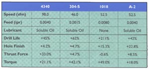
Table 1: Drilling conditions and improvement results for laboratory test comparing cryogenically treated and untreated tools. (Click for larger image)
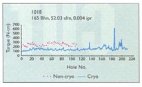
Figure 1: Comparison of drilling torgue for crygenically and untreated twist drills when machining 1018 steel.
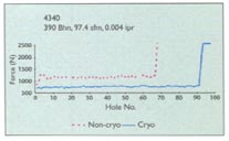
Figure 2: comaprison of drilling thrust force for cryogenically and untreated twist drills when machining 4340 steel. (Click for larger image)We conducted the drilling tests on four commonly machined materials: 1018 low-carbon steel (165 Bhn), 340 alloy steel (390 Bhn), A-2 tool steel (175 Bhn), and 304-S stainless steel (126 Bhn). We used M-1 HSS drills with 118° point angles. Drilling conditions and test results are reported in Table 1.
For all materials, we observed a significant increase in tool life, which we measured as the number of holes produced before drill failure. Better hole finish and roundness complemented this improved tool performance.
These measurements were made over the useful life of the drill, but Table 1 compares holes produced by unworn tools. The improvements in hole roughness ranged from modest for 4340 and 304-S to dramatic for 1018 and A-2. We also measured significant decreases in both drilling thrust force and torque for all materials tested. Figure 1 illustrates the difference in measured torque when drilling AISI 1018 steel, and Figure 2 shows the difference in thrust force when drilling 4340.
In addition, we conducted turning tests on AISI 4340 (226 Bhn). We used T-15 tool-steel inserts at cutting speeds of 200 and 300 sfm, a constant feed of 0.0075 ipr, and a 0.050" depth of cut. The cryogenically treated and untreated inserts had a tool signature of (0°, 5°, 11°, 11°, 15°, 15°, 1Ú32"). At both speeds, tool life was significantly longer, with flank wear being the dominant wear mode. At 200 sfm, the cryogenically treated inserts lasted 127.0% longer than the untreated inserts (2180 min. vs. 960 min.), and at 300 sfm, the cryogenically treated inserts lasted 91.4% longer than the untreated inserts (155 min. vs. 81 min.).
In the Field
After complete testing in the laboratory, we compared the drilling results to field data reported by Nu-Bit Inc. In all cases the field-test results showed significantly greater increases in drill life than the laboratory results. Compared to untreated drills, cryogenically treated M-1 tool-steel drills used by tool-and-die, automotive, and job shops lasted 200% to 300% longer in the machining of 304-S, 100% longer in the machining of 4340, and 425% longer in the machining of 1018-CR. Variations in workpiece properties, use of somewhat different cutting conditions, and varying criteria for tool failure account for the differences between the results in the field and the results in the laboratory.
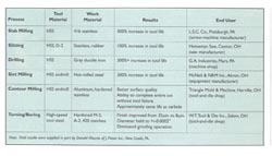
Table 2: Results of fields tests comparing cryogenically treated and untreated tools used in various maching processes.We carried out additional field tests to assess the impact of deep cryogenics on other processes and materials not tested in the laboratory. The results are shown in Table 2 and in the sidebar on the left. In all cases, tool life was dramatically improved, even when a lower grade of steel was used. The results of the contour-milling test revealed a better surface finish, which is consistent with the laboratory results for drilling.
Users in the field have found cryogenic treatment of cutting tools to be quite economical. The average cost of the treatment is generally 15% of the tool cost. When properly applied, cryogenic treatment also has the potential to decrease processing costs and improve part quality. The key is to integrate cryogenics into the heat-treatment cycle rather than to use it as an "added-on" process.
About the Authors
Paul H. Cohen, Ph.D., is professor of industrial engineering and director of the Machining Research Laboratory, Department of Industrial and Manufacturing Engineering, Pennsylvania State University, University Park, PA. Dennis J. Kamody is president of Nu-Bit Inc., New Kensington, PA.
Related Glossary Terms
- austenite
austenite
Solid solution of one or more elements in face-centered cubic iron. Unless otherwise designated (such as nickel austenite), the solute is generally assumed to be carbon. Austenite can dissolve up to 2 percent carbon. Austenite is relatively soft, ductile and nonmagnetic.
- depth of cut
depth of cut
Distance between the bottom of the cut and the uncut surface of the workpiece, measured in a direction at right angles to the machined surface of the workpiece.
- feed
feed
Rate of change of position of the tool as a whole, relative to the workpiece while cutting.
- flank wear
flank wear
Reduction in clearance on the tool’s flank caused by contact with the workpiece. Ultimately causes tool failure.
- high-speed steels ( HSS)
high-speed steels ( HSS)
Available in two major types: tungsten high-speed steels (designated by letter T having tungsten as the principal alloying element) and molybdenum high-speed steels (designated by letter M having molybdenum as the principal alloying element). The type T high-speed steels containing cobalt have higher wear resistance and greater red (hot) hardness, withstanding cutting temperature up to 1,100º F (590º C). The type T steels are used to fabricate metalcutting tools (milling cutters, drills, reamers and taps), woodworking tools, various types of punches and dies, ball and roller bearings. The type M steels are used for cutting tools and various types of dies.
- martensite
martensite
Formed during rapid cooling of austenite at the temperature rate higher than 500º F (260º C) per second. Such rapid cooling causes restructuring of crystalline lattice of gamma iron into crystalline lattice of alpha iron in which carbon is fully dissolved. Because only 0.04 percent carbon can be dissolved in alpha iron, the excessive amount of carbon transforms into supersaturated solution of carbon in alpha iron. This type of solution is called martensite, which is characterized by an angular needlelike brittle structure and high hardness (greater than 60 HRC).
- metalworking
metalworking
Any manufacturing process in which metal is processed or machined such that the workpiece is given a new shape. Broadly defined, the term includes processes such as design and layout, heat-treating, material handling and inspection.
- microstructure
microstructure
Structure of a metal as revealed by microscopic examination of the etched surface of a polished specimen.
- turning
turning
Workpiece is held in a chuck, mounted on a face plate or secured between centers and rotated while a cutting tool, normally a single-point tool, is fed into it along its periphery or across its end or face. Takes the form of straight turning (cutting along the periphery of the workpiece); taper turning (creating a taper); step turning (turning different-size diameters on the same work); chamfering (beveling an edge or shoulder); facing (cutting on an end); turning threads (usually external but can be internal); roughing (high-volume metal removal); and finishing (final light cuts). Performed on lathes, turning centers, chucking machines, automatic screw machines and similar machines.