A clear view on vision panels

Author Dr. Scott Smith
Published
February 01, 2015 - 10:30am

The cutting zone in a machine tool is dangerous. Hot chips and large quantities of coolant are often safety threats, but a tool rotating at a high speed is an even greater one. In addition, the workpiece in a turning center often has a large mass. Tool breakage, clamp failures, crashes and other accidents may generate high-energy projectiles, requiring enclosures to protect shop personnel.

When turning, clamps and workpieces are the main concern, so enclosure designers target masses of at least 2.5 kg. When milling, pieces of the cutting tool may be ejected, so projectiles with a mass below 100 grams pose a concern. In both cases, the projectile energy can be quite high.

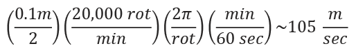
The peripheral velocity of a rotating tool is given by r × ω, where r is the tool radius, and ω is the rotational speed in radians per second. For a 100mm-dia. milling tool rotating at 15,000 rpm, the peripheral velocity (same as the cutting speed) is:

26731.png

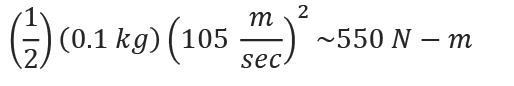
That is about a quarter to half the muzzle velocity of a handgun. The energy contained in a projectile increases with the square of the velocity, E = ½ × m × v2. The energy contained in a 100-gram projectile traveling at 105 m/sec. is:

26755.png

When turning a 300mm-dia. workpiece at a spindle speed of 1,500 rpm, the peripheral velocity is about 25 m/sec., and the energy contained in a 2.5-kg projectile is about 780 Nm. Needless to say, it is important to keep the guard doors closed when a workpiece is rotating.

Yet at the same time, the operator often needs to see the machining operation. Most machine tool enclosures incorporate transparent, impact-resistant panels for vision purposes. A material like polycarbonate, which is used in safety glasses, would seem like an effective choice, given that a single transparent polycarbonate sheet only has to be about 2.7 times thicker than a steel sheet to provide the same impact resistance.

However, a study by the German Machine Tool Builders’ Association (VDW) found that polycarbonate panels can become brittle. Polycarbonate material is somewhat porous and becomes more so when the surface is scratched. Coolant and cleaning fluids attack and penetrate the polycarbonate material, causing it to become brittle. The panels sometimes become difficult to see through as well, leading the operator to open the enclosure.

26786.png

Figure 1. Exposure to cutting fluids can cause plain polycarbonate vision panels to rapidly lose their impact resistance.

The VDW study found that polycarbonate windows exposed to fluids may lose about 40 percent of their impact resistance within 2 years and 60 percent within 4 years (Figure 1). As a result, end users should regularly replace plain polycarbonate vision panels, even if they have not been involved in an accident. On the other hand, vision panels that have not been exposed to cutting or cleaning fluids can retain most of their impact resistance for a decade or longer.

An alternative to regular replacement of viewing panels is the use of composite panes made of safety glass and polycarbonate (Figure 2). The safety glass on the work zone side of the pane is impervious to fluid. While it is hard and resists scratches, it has little impact resistance. It functions mainly to protect the polycarbonate from chemical attack by fluids.

26786.png

Figure 2. The construction of a composite pane.

The polycarbonate on the operator side of the pane provides almost all of the impact resistance. A thin, flexible polymer interlayer bonds the glass and the polycarbonate to create the pane. In the event of a projectile impact, the interlayer holds the pieces of the composite pane together, similar to how automotive safety glass works.

In addition, the interlayer’s flexibility allows for a difference in coefficient of thermal expansion between the glass and the polycarbonate. Almost all of the impact resistance is provided by the polycarbonate portion of the panel. Its thickness is chosen based on the energy of potential projectiles.

In this configuration, the polycarbonate section of the pane is still open to embrittlement from the operator side. An even stronger and more durable configuration would repeat the flexible interlayer and safety glass layers on the operator side of the sandwich. CTE

Related Glossary Terms

  • coolant

    coolant

    Fluid that reduces temperature buildup at the tool/workpiece interface during machining. Normally takes the form of a liquid such as soluble or chemical mixtures (semisynthetic, synthetic) but can be pressurized air or other gas. Because of water’s ability to absorb great quantities of heat, it is widely used as a coolant and vehicle for various cutting compounds, with the water-to-compound ratio varying with the machining task. See cutting fluid; semisynthetic cutting fluid; soluble-oil cutting fluid; synthetic cutting fluid.

  • embrittlement

    embrittlement

    Reduction in the normal ductility of a metal due to a physical or chemical change. Examples include blue brittleness, hydrogen embrittlement and temper brittleness.

  • gang cutting ( milling)

    gang cutting ( milling)

    Machining with several cutters mounted on a single arbor, generally for simultaneous cutting.

  • milling

    milling

    Machining operation in which metal or other material is removed by applying power to a rotating cutter. In vertical milling, the cutting tool is mounted vertically on the spindle. In horizontal milling, the cutting tool is mounted horizontally, either directly on the spindle or on an arbor. Horizontal milling is further broken down into conventional milling, where the cutter rotates opposite the direction of feed, or “up” into the workpiece; and climb milling, where the cutter rotates in the direction of feed, or “down” into the workpiece. Milling operations include plane or surface milling, endmilling, facemilling, angle milling, form milling and profiling.

  • turning

    turning

    Workpiece is held in a chuck, mounted on a face plate or secured between centers and rotated while a cutting tool, normally a single-point tool, is fed into it along its periphery or across its end or face. Takes the form of straight turning (cutting along the periphery of the workpiece); taper turning (creating a taper); step turning (turning different-size diameters on the same work); chamfering (beveling an edge or shoulder); facing (cutting on an end); turning threads (usually external but can be internal); roughing (high-volume metal removal); and finishing (final light cuts). Performed on lathes, turning centers, chucking machines, automatic screw machines and similar machines.

Author

Dr. Scott Smith is a professor and chair of the Department of Mechanical Engineering at the William States Lee College of Engineering, University of North Carolina at Charlotte, specializing in machine tool structural dynamics. Contact him via e-mail at kssmith@uncc.edu.

Click on the author to view all of their articles!