Incorporating in-machine deburring.
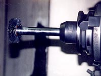
 By inserting nylon abrasive wheel brushes into the bore of a connecting rod, burrs on oil holes and similar edges can be removed. |
|
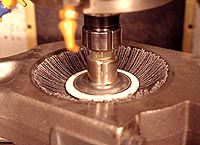
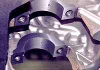
 The faces of a connecting rod are deburred after facemilling using a disc brush fed across the part at 15 ipm with a 0.125” depth of interference. |
|
A different type of cutting tool is appearing in toolchangers throughout the machining world. This tool isn’t made of cermet, carbide or HSS. It doesn’t have a rake angle or chipbreaker geometry. In fact, it doesn’t even come in a brightly colored plastic box.
Nonetheless, this tool—the nylon abrasive-filament brush—is showing up in machining centers everywhere. Why? Because deburring is an intimate part of the machining process. Often, deburring has dimensional and surface-finish ramifications that are as important to overall part quality as the machining process.
As a result, combining operations allows a manufacturer to consolidate the accountability for dimensional accuracy into a single step. This provides two benefits: improved system economics and enhanced part flow.
Improving Economics
Single-point accountability for machining and deburring encourages optimization of the combined process for quality and productivity. Variations in burr size due to changes in machining parameters can be immediately detected and controlled in this type of single-part-flow arrangement.
If machining and deburring operations are viewed as standalone processes, the natural tendency is to try and optimize them individually. While this approach can produce positive results, it rarely creates the best, most efficient system possible.
The following equation can be used to determine the efficiency of a combined machining/deburring process:
where: |
There are seven variables in this equation and, therefore, seven areas in which to improve production performance. Including them in the same equation allows operators and engineers to calculate the trade-offs between alternative operating parameters. It spurs questions like, “Does the financial benefit of a machining-parameter change offset any higher deburring costs that result?” The following are a few of the trade-offs that can arise.
Tool path selection vs. deburring cost. Not all tool paths produce burrs that are the same size. In some cases, simple changes to the tool path can significantly reduce burr size. In cases where improved machining reduces the burr size, deburring costs can be reduced correspondingly.
Tool-change frequency vs. deburring cost. Since cutting tools represent a considerable expense in the manufacturing process, their use needs to be managed carefully. However, tool-change frequencies should take the deburring cost into consideration. If the economics dictate that extending tool use warrants the higher deburring cost, then an educated decision has been made.
In many cases, direct labor reductions, applied overhead reductions and reduced rework costs can justify the time that is added to a machining operation by incorporating deburring into the cycle.
An automobile manufacturer recently realized this trade-off in a very painful way. The automaker changed the type of cutting tool it used in order to lower costs. The downside was that the change led to significantly larger burrs on the workpiece.
As a result of the larger burrs, the costs for consumable deburring tools more than doubled and associated labor skyrocketed. A review of the process efficiency of combining machining and deburring would have shown that the reduction in cutting tool costs could not be justified based on the increased deburring costs.
Scrap/rework vs. machining parameters. For manufacturers of high-value-added parts, scrap and rework is an expensive proposition. When burrs get too large and cannot be removed using established deburring processes, rework is usually required. Combining the machining and deburring operations virtually eliminates the cost of the rework/scrap resulting from burr variation.
Value of machining time vs. cost of a secondary deburring process. The greatest value of in-machine deburring is the elimination of a secondary operation. In many cases, direct labor reductions, applied overhead reductions and reduced rework costs can justify the time that is added to a machining operation by incorporating deburring into the cycle.
Although these trade-offs do not constitute a comprehensive list, they illustrate that a “big-picture” perspective on cost reductions is important and can be achieved by consolidating machining and deburring into a single operation.
Improving Part Flow
 Wheel brushes can be interpolated in the bores of cylinder heads using tool paths that account for the numerous bore-size changes. |
|
In addition to enhanced system economics, in-machine deburring simplifies part flow and produces related operational advantages.
For example, consider the following case history of a manufacturer that performs milling and deburring operations on aluminum pump components. After the parts are machined, they are placed in baskets and moved to the parts cleaning/deburring department, which has several deburring systems. These include burr benches, tumbling units and an extrusion deburring machine.
In this production system, the work-in-process (WIP) inventory sits at multiple locations in the plant. After machining, the parts are stored in baskets at the machining center and then moved to the parts cleaning/deburring department where they wait to be processed. After deburring, the parts are staged before going to the shipping department.
In the shipping department, the parts are packaged and shipped to the assembly plant. With this part flow, the normal lead time from machining to shipping is two to three weeks. The processing time is a small fraction of the total lead time, but the parts are queued and processed in batches based on available resources and departmental priorities.
Under pressure to reduce lead time and capital allocated to WIP, the manufacturer implemented in-machine deburring. Doing this did not require a major capital investment, and it allowed the parts to flow directly from the machining center to the shipping department, eliminating two queue locations. The result was a 50 percent reduction in lead time and WIP.
In addition, removing several high-volume parts from the parts cleaning/deburring department shortened the queues in that area and created additional WIP reductions.
In this case, the part flow could have been improved by moving the burr benches from the parts cleaning/deburring department to the machining center. This option was not pursued because in-machine deburring offered better part consistency and fit into the plant’s long-term goal of establishing untended machining processes wherever possible.
Regardless of the deburring method, the key to a successful deburring operation is burr minimization. The selection of the proper cutting tools, tool paths and tool-change frequencies can significantly reduce burr size. If burr minimization through improved machining is not sufficient to produce the dimensional results and surface finishes required, nylon abrasive-filament brushes are an extremely effective in-machine solution.
Selective Aggression
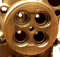 After in-machine deburring, this cylinder head doesn’t require any manual deburring. |
|
Nylon abrasive-filament brushes are “edge-selective aggressive.” This means that the brush’s filaments act aggressively when applied to an edge but not on flat surfaces. As a result, they refine surface finishes without measurably changing part dimensions.
This selective cutting action is due to the pressure-sensitive nature of nylon abrasive brushes. When a filament is filing across an edge, the cutting pressure is high due to the small contact area. However, the pressure drops dramatically when the same filament begins to move across a flat surface. Hence, a brush that produces a 0.015" radius on an exotic aerospace part also can be used to reduce the surface finish on a camshaft to under 20µin.
Typically, nylon abrasive brushes can be used in CNC equipment by copying the existing machining programs and making slight changes. For example, the tool path for a disc brush is very similar to the tool path for a facemill. The major differences are the required spindle speed, feed rate and depth of interference (analogous to DOC).
In some operations, it is also necessary to take two passes across the part, with the brushes rotating in opposite directions for each pass. The need for two passes is based on burr size and orientation.
Unlike cutting tools, nylon abrasive brushes do not require exact positioning. The brushes easily conform to various shapes, making them extremely forgiving. Typically, positioning within 0.030" of the ideal location will produce acceptable results. Although this window of acceptability varies with brush size and application, most operating windows are large and do not require significant programming time to achieve. This ability to handle part variation is especially beneficial on castings, because the brushes compensate for casting tolerances.
The most complicated aspect of an in-machine deburring application relates to the location and style of clamping fixtures. In CNC machining centers with horizontal spindles, parts are commonly fixtured with clamps that reach around the edges of the part. Although these clamps do not interfere with cutting tool paths, they occasionally interfere with brushes that are often larger than cutting tools. If clamps interfere with the flow of filaments toward the target edge, they may need to be repositioned or exchanged for a clamp that does not reach past the edge of the part.
Case Histories
The following examples of in-machine deburring are from the diesel engine manufacturing industry, where nylon abrasive brushes are used to deburr and radius- and surface-finish engine parts.
Connecting Rods. Two applications exist for connecting rods. The first is deburring the face of the connecting rod after facemilling. This application involves feeding a disc brush across the part at a rate of 15 ipm and a 0.125" depth of interference. This deburring step can be easily accomplished while the part is fixtured for facemilling.
Unlike cutting tools, nylon abrasive brushes do not require exact positioning. The brushes easily conform to vaious shapes, making them extremely forgiving.
The second application is to deburr the crank bore (and wrist-pin bore in some cases) after machining. Nylon abrasive wheel brushes are well suited for bore deburring. By interpolating a brush in the bore, burrs created on oil holes and similar edges can be removed.
The connecting rods in this case are large (a crank bore exceeds 10") and made of alloy steel. The exit burrs on the crank bore that result from the boring operation are extremely large, with a root thickness of more than 0.020". Since burrs of this type cannot be removed with nylon abrasive brushes, the user designed a cutting tool that removed the primary burr. After removing the large burr with a cutting tool, the secondary burr was easily removed with a nylon abrasive brush, which also produced an edge radius of about 0.005".
This is an excellent example of the efficiency gains that can be achieved by combining machining and deburring operations. In addition to productivity gains in excess of 20 percent, the user said that the greatest benefit of the in-machine deburring solution was consistent part quality. Every connecting rod on every shift received the same amount of deburring. As a result, resources spent resolving quality complaints were reduced and the process engineers could spend time working on projects that offered a payback rather than resolving deburring problems.
Cylinder Heads. The steps in the bore of a cylinder head have microburrs that must be removed and nylon abrasive wheel brushes are ideal for this application. Wheel brushes can be interpolated in each of the bores using tool paths that account for the numerous changes in bore size. Following the deburring operation, all of the sharp edges are broken and the part does not require any manual deburring.
One critical operating parameter for nylon abrasive brushes is speed. Surface speed should always be less than 3,500 sfm. Excessive speed prevents the brushes from working effectively because the filaments do not have sufficient time to file across the part edges. In addition, excessive speed generates heat, which can cause the filaments to begin to soften and melt. In a softened state, the filaments lose nearly all of their deburring ability.
 Engine blocks are ideal candidates for in-machine deburring. A disc brush is rotated in the opposite direction of the cutting tool and is fed along a similar tool path. |
|
Engine Blocks. Many engine-block surfaces have burrs resulting from various milling operations. One such surface is a crankshaft bearing journal. A disc brush can effectively deburr this type of surface. It is rotated in the opposite direction of the cutting tool and is fed along a similar tool path. At 15 ipm, the brush uniformly deburrs the sharp edges left by the machining operations.
Machining and deburring are related elements of the same process—producing a part with the dimensional and surface finish characteristics that the customer requires. Keeping these processes separate will raise operating costs and extend lead times.
Implementing in-machine deburring with nylon abrasive brushes is an inexpensive way to make operational improvements with a quick payback.
About the Author
John Sockman is the power brush market manager at Weiler Corp., Cresco, Pa.
Related Glossary Terms
- abrasive
abrasive
Substance used for grinding, honing, lapping, superfinishing and polishing. Examples include garnet, emery, corundum, silicon carbide, cubic boron nitride and diamond in various grit sizes.
- boring
boring
Enlarging a hole that already has been drilled or cored. Generally, it is an operation of truing the previously drilled hole with a single-point, lathe-type tool. Boring is essentially internal turning, in that usually a single-point cutting tool forms the internal shape. Some tools are available with two cutting edges to balance cutting forces.
- burr
burr
Stringy portions of material formed on workpiece edges during machining. Often sharp. Can be removed with hand files, abrasive wheels or belts, wire wheels, abrasive-fiber brushes, waterjet equipment or other methods.
- centers
centers
Cone-shaped pins that support a workpiece by one or two ends during machining. The centers fit into holes drilled in the workpiece ends. Centers that turn with the workpiece are called “live” centers; those that do not are called “dead” centers.
- chipbreaker
chipbreaker
Groove or other tool geometry that breaks chips into small fragments as they come off the workpiece. Designed to prevent chips from becoming so long that they are difficult to control, catch in turning parts and cause safety problems.
- computer numerical control ( CNC)
computer numerical control ( CNC)
Microprocessor-based controller dedicated to a machine tool that permits the creation or modification of parts. Programmed numerical control activates the machine’s servos and spindle drives and controls the various machining operations. See DNC, direct numerical control; NC, numerical control.
- extrusion
extrusion
Conversion of an ingot or billet into lengths of uniform cross section by forcing metal to flow plastically through a die orifice.
- facemill
facemill
Milling cutter for cutting flat surfaces.
- facemilling
facemilling
Form of milling that produces a flat surface generally at right angles to the rotating axis of a cutter having teeth or inserts both on its periphery and on its end face.
- feed
feed
Rate of change of position of the tool as a whole, relative to the workpiece while cutting.
- filing
filing
Operation in which a tool with numerous small teeth is applied manually to round off sharp corners and shoulders and remove burrs and nicks. Although often a manual operation, filing on a power filer or contour band machine with a special filing attachment can be an intermediate step in machining low-volume or one-of-a-kind parts.
- flat ( screw flat)
flat ( screw flat)
Flat surface machined into the shank of a cutting tool for enhanced holding of the tool.
- gang cutting ( milling)
gang cutting ( milling)
Machining with several cutters mounted on a single arbor, generally for simultaneous cutting.
- high-speed steels ( HSS)
high-speed steels ( HSS)
Available in two major types: tungsten high-speed steels (designated by letter T having tungsten as the principal alloying element) and molybdenum high-speed steels (designated by letter M having molybdenum as the principal alloying element). The type T high-speed steels containing cobalt have higher wear resistance and greater red (hot) hardness, withstanding cutting temperature up to 1,100º F (590º C). The type T steels are used to fabricate metalcutting tools (milling cutters, drills, reamers and taps), woodworking tools, various types of punches and dies, ball and roller bearings. The type M steels are used for cutting tools and various types of dies.
- inches per minute ( ipm)
inches per minute ( ipm)
Value that refers to how far the workpiece or cutter advances linearly in 1 minute, defined as: ipm = ipt 5 number of effective teeth 5 rpm. Also known as the table feed or machine feed.
- machining center
machining center
CNC machine tool capable of drilling, reaming, tapping, milling and boring. Normally comes with an automatic toolchanger. See automatic toolchanger.
- milling
milling
Machining operation in which metal or other material is removed by applying power to a rotating cutter. In vertical milling, the cutting tool is mounted vertically on the spindle. In horizontal milling, the cutting tool is mounted horizontally, either directly on the spindle or on an arbor. Horizontal milling is further broken down into conventional milling, where the cutter rotates opposite the direction of feed, or “up” into the workpiece; and climb milling, where the cutter rotates in the direction of feed, or “down” into the workpiece. Milling operations include plane or surface milling, endmilling, facemilling, angle milling, form milling and profiling.
- rake
rake
Angle of inclination between the face of the cutting tool and the workpiece. If the face of the tool lies in a plane through the axis of the workpiece, the tool is said to have a neutral, or zero, rake. If the inclination of the tool face makes the cutting edge more acute than when the rake angle is zero, the rake is positive. If the inclination of the tool face makes the cutting edge less acute or more blunt than when the rake angle is zero, the rake is negative.