CBN Wheels in Peak Condition
CBN Wheels in Peak Condition
CBN grinding wheels offer the promise of higher productivity and longer wheel life, but they must be carefully maintained with dressing routines that differ from routines for standard wheels. This article details the techniques and tools needed to perform CBN wheel dressing effectively and economically.
| Refinements in the dressing process and advances in adaptive controls are helping users get the most out of their CBN wheels.
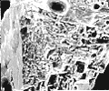
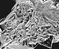
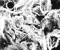
Without vitrified bonds, shops wouldn't be able to use cubic-boron-nitride (CBN) abrasive wheels for high-volume production applications. Only these porous bond materials provide the necessary chip clearance, coolant access, and dressability manufacturers require to grind ferrous metals in production applications using CBN. Grinding-systems manufacturers have learned much since vitrified-bond CBN wheels were introduced 10 years ago. At first, manufacturers believed that shops could use the same rules they used to true and dress conventional-abrasive wheels in one operation to true and dress CBN wheels. In theory, the vitrified bond's brittleness and crushability would make this possible. Experience has shown, however, that the practices of the day were not applicable to the newer CBN wheels. To achieve optimal wheel performance from a combined truing and dressing process (commonly referred to as "dressing"), the manufacturers had to determine a whole new range of working parameters and limitations. Out of this search for better practices came major advances in CBN-wheel dressing and machine-control technology. The Dressing Process Before these systems manufacturers could devise new ways to dress CBN wheels, they had to understand the dynamics and calculate the economics of the CBN-wheel dressing process. Like diamond, CBN is a high-cost abrasive. Therefore, wheel manufacturers had to develop a dressing process that removed no more CBN than was necessary so that users could grind as many parts as possible before discarding the wheel. Typically, an area only a few microns thick needs to be removed from the CBN wheel's surface to resharpen the wheel. At the same time, grinding-systems manufacturers had to find the most effective way to expose new cutting edges on the abrasive grains. The typical abrasive chosen for study was Type I Borazon CBN, a black, angular crystal manufactured by GE Superabrasives, Worthington, OH. This grade is most often used for production grinding. By introducing controlled levels of defects at the submicron level as the abrasive is synthesized, GE is able to influence the grain's cleavage characteristics and produce a grain with very well-controlled fracture strength. Similar grades of CBN abrasives from other manufacturers are believed to possess comparable fracture characteristics. When researchers analyzed the Borazon grade, they found that the rate of infeed during the dressing process and the crush ratio strongly influence the way the grains fracture. To derive the crush ratio, divide the rotational speed of the dresser roll (expressed as surface feet per minute) by the grinding speed of the wheel (expressed as surface feet per minute). A positive crush ratio means the wheel and dresser roll are moving in the same direction at the point of contact. In one study of vitrified-bond wheels containing B181 GE Type I CBN, the wheels were dressed with a traversing rotary diamond at a crush ratio of +0.2. When the wheel surface was dressed to an infeed depth of 1µm, the CBN grains were cleaved by microfracture. This means that the dressing process produced micron-level fractures in the grains. Microfracture helps conserve abrasive, because it leaves a high surface concentration of grains with a large number of small cutting edges (Figure 1A). When the dressing was increased to a depth between 2µm and 3µm, the researchers saw evidence of macrofracture. When macrofracture occurs, a significant portion of the abrasive grain is lost. The result is a wheel surface with fewer but sharper cutting edges (Figures 1B and 1C). This creates a much freer cutting surface, but the large-scale loss of expensive abrasive reduces grit surface concentration, curtailing the wheel's performance life and making the process less cost-effective. These results showed researchers how easily the effectiveness of the dressing process can be influenced by small changes in the dresser infeed. To make the fine adjustments necessary, CBN-wheel users must have a dresser-infeed mechanism that offers micron resolution. Changes in the crush ratio produced results similar to those seen at greater dressing depths. With the dresser and wheel rotating in the same direction to induce high normal grinding force, the dressing process removed the brittle vitrified bond to a greater depth than it removed the abrasive. As the crush ratio was increased from +0.2 to +0.8, more bond was removed. However, the degree of grain macrofracture also increased. Even when the infeed depth was set at 1µm, large portions of the grains were broken off. According to these results, users should not always assume a high crush ratio is better because it removes more bond. If the crush ratio also leads to greater macrofracture, the dressing process may result in accelerated wheel wear. The change from microfracture to macrofracture caused by increases in the crush ratio and infeed depth was particularly noticeable when the researchers dressed wheels with larger grit sizes such as those used for grinding wheel is fed into the outside surface in controlled relation to the axis of rotation. Th…" title="Grinding operation in which the workpiece is rotated around a fixed axis while the grinding wheel is fed into the outside surface in controlled relation to the axis of rotation. Th…" aria-label="Glossary: cylindrical grinding">cylindrical grinding. This is because the larger grains are more likely to have flaws that become the starting points for fracture. It is also easier to tell the difference between the two types of fracture when examining the larger grains. Through other studies, the CBN-wheel manufacturers learned the importance of using a proper dress traverse rate to ensure proper contact between the dresser roll and each CBN grain on the wheel. Ideally, each grain should be cleaved by a single impact with a diamond on the dresser roll. If the average number of impacts is less than one per grain, the process leaves some grains untouched and dull. A traverse rate that causes, on average, more than one impact between the diamond and each grain effectively dresses each grain more than once. Because each impact after the first occurs at a finer infeed due to the lower height of the fractured grain, an infeed rate that results in multiple impacts generates a relatively dull surface. Manufacturers have refined their dresser designs over the years to control this impact value. Users now find it relatively simple to achieve the correct dress action and, furthermore, to calculate appropriate dress traverse rates for a given grinding-wheel rpm and CBN-grit size. Wheel manufacturers also studied the changes in a vitrified-bond CBN wheel's surface caused by dressing and use. They found that dressing creates a surface layer with a lower concentration of CBN and less vitrified-bond material than the bulk of the wheel. The affected layer, which is also created on vitrified-bond conventional-abrasive wheels, is termed "tsukidashiryo," or active surface roughness. This layer can vary from a few microns to more than 30µm in depth. Subsequent use of the wheel usually increases the depth of this layer and accentuates its effects on the wheel's surface. Dressing after use should eliminate the deeper and more accentuated tsukidashiryo that use produces. This is almost always the case when vitrified-bond conventional-abrasive wheels are dressed, because the infeed depths are typically much greater than they are with vitrified-bond CBN-wheel dressing. The added depth ensures that most or all of the layer affected by grinding is removed and a fresh surface layer is created with CBN and bond concentrations determined solely by the dressing parameters. But when vitrified-bond CBN wheels are dressed, the total dress depth can be much shallower than the depth of the affected layer. This allows the history of the wheel's surface prior to dressing to have a profound effect on the wheel's performance after dressing. A depth of dress that is not great enough to remove all of the affected layer can reduce the subsequent parts-per-dress, while a depth that is too great can actually dull the wheel. To fully restore a CBN wheel, a user may have to dress it to a much greater depth than is considered normal for such wheels. For example, in one experiment with B181 CBN wheels for cylindrical grinding, a depth of 20µm had to be dressed from the wheel to restore surface integrity and the original grinding-force levels. The researchers also found that a wheel's G ratio and its ability to grind a finish below a specified value increased by a factor of 4 when dressing consisted of four passes at 2µm, compared to just one pass at 2µm. The shallow infeed per pass kept the incidence of macrofracture to a minimum, while the total depth of dress eliminated the affected layer.
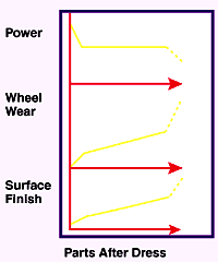
The Break-In Period By studying the characteristics of CBN and the vitrified bond, manufacturers have been able to refine the dressing process. But even when the dressing process is optimized according to these findings, the wheel will require a break-in period to allow the grinding process to remove weakly bonded abrasive and residual bond left from dressing. Typically, performance will follow curves similar to those plotted in Figure 2, which show how normal grinding force, wheel wear, and surface finish change as the wheel grinds an increasing number of parts after it has been dressed. Immediately after dress, normal grinding force is relatively high, but this force drops quickly as the wheel grinds the first few parts. Typically, 2% to 10% of the total number of components ground per dress will be affected by these rapid changes. During this period of inconsistent wheel performance, part quality suffers because of higher part and wheel/spindle deflection. During this same period, the wheel wears more quickly, and it can produce a rapid increase in surface roughness. To avoid these problems, the user would have to assess the wheel's performance after every part and make the necessary adjustments before grinding the next part. The history of the wheel's dressing and use and the grinding process's effect on the wheel's tsukidashiryo will determine the magnitude of the drop in normal grinding force after dress. Generally, a new wheel will have a much larger drop in normal grinding force than one that has gone through several dressing cycles. The wheel becomes conditioned through use as the grinding action wears the bond away from the grains, and this results in lower grinding force immediately after dressing than is the case with a new wheel. After the initial break-in period, there is a much slower rate of wear accompanied by a more gradual increase in finish values and a reduction in normal grinding force. This is associated with a steady increase in tsukidashiryo and wheel sharpness as the grinding process wears away the bond. Eventually, there is too little bond left to hold the grains, and the wheel wears rapidly. At this point, wear reduces the wheel's diameter so extensively that the surface is no longer in contact with the workpiece, and normal grinding force rapidly drops. A Touch of Precision Manufacturers of CBN wheels for cylindrical and internal grinding have developed technologies to compensate for the dressing process's limitations and its sensitivity to the infeed-per-pass ratio, total dress infeed, crush ratio, and traverse rate. These compensations have taken the form of touch sensors and adaptive controls. To dress cylindrical-grinding wheels, manufacturers had to design a system that could dress wheels consistently within the narrow range of depths appropriate for the operation. Cylindrical-grinding systems are relatively stiff, so changes in normal grinding force typically do not diminish part quality. This allows the user to dress the wheel to a minimal surface finish, making sure only that the surface isn't so smooth that it burns the part. To produce a wheel with the desired characteristics, the user selects dress parameters that will generate primarily microfracture and maintain a high concentration of CBN on the surface.
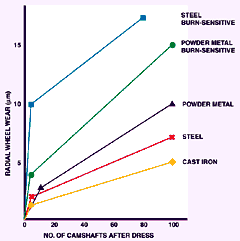
Figure 3 plots typical wheel-wear curves for various cylindrical-grinding applications employing different CBN-wheel specifications to grind a range of camshaft materials. As the graph shows, wear is typically 2µm to 3µm at the beginning of a cylindrical-grinding application, although in the most extreme cases it can be as great as 10µm. To grind the maximum number of parts per dress, users may allow the wheel to wear as much as 15µm or more before dressing. To restore the correct tsukidashiryo on these worn wheels, a user must dress several microns from the wheel. Therefore, typical dressing parameters are: Crush ratio = +0.2 - +0.5 The greatest difficulty in maintaining these parameters consistently from dress to dress is thermal movements within the machine. In the time between dresses, the temperature of the machine may drift enough to make positional errors between the dresser and the wheel greater than the amount to be dressed. To detect and compensate for these errors, a wheel user needs some means to accurately determine the relative positions of the dresser and the wheel. Most methods currently in use determine the dresser and wheel positions by sensing when the dresser actually touches the grinding wheel. Some methods monitor power or force to detect contact. Force monitoring using piezoelectric or strain gages is popular for internal grinding. One novel method uses a stack of piezoelectric elements to detect force and then carry out the infeed movement of the dresser. Other monitoring methods use acoustic emission. AE sensors have proven the most effective and simplest method to apply for cylindrical grinding. Several systems are commercially available. Working in the frequency range of 50 to 600 kHz, these sensors are tuned to pick up the sound of the dresser diamonds striking the CBN grits. Most units can be adjusted to pick up the appropriate frequency for a given wheel speed or grit size. Manufacturers have found that the mounting hardware and the sensor's location on the machine have a significant impact on the sensor's performance. If the AE sensor is not fitted properly to the machine, the spindle-bearing noise masks the signal. Manufacturers also have found that when the sensor is mounted on the dresser-spindle body, the signal tends to be attenuated through the bearings. Users can evaluate the ratio of signal-to-noise by examining an analog-signal output. Most AE systems can provide a graphic representation of the signals they are receiving. On these plots, the dresser striking the wheel will show as a spike against the lower-level background noise. Early methods developed by sensor manufacturers to ensure a clear signal employed a water coupling. The sensor was mounted adjacent to the dresser, and hydraulic fluid or coolant was used as a sound medium between the sensor and the dresser body. By allowing the sensor to be mounted at a distance from the dresser, the coupling increased the signal-to-noise ratio. With a good laminar flow of coolant, the sensor could be mounted up to 300mm away, though usually it was mounted within 5mm.
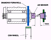
A preferred mounting method employs a signal analyzer and transmitter. A sensor with a built-in analyzer and transmitter is mounted on the body of the dresser. The transmitter sends a signal across a small gap to a receiver (Figure 4). There are several hundred of these systems in use today. Researchers at the Landis/Gardner/Citco division of Western Atlas, Waynesboro, PA, tested the effectiveness of AE for touch sensing using an analyzer/transmitter mounted on a CNC camlobe grinder. The machine was equipped with a high-frequency dresser spindle, diamond dresser, and vitrified-bond CBN wheel. Before dressing, the wheel was used to grind several narrow components. This application produced a wear band in the center of the wheel face. To initiate dressing, the researchers moved the dresser approximately 50µm from the wheel face and traversed the dresser across the face of the wheel while infeeding the dresser progressively at 2.5µm per pass. Once the sensor detected a signal above a trip amplitude at every point as the dresser traversed the wheel face, a final pass with a 1µm infeed was made. When the dresser first came in contact with the wheel, the sensor picked up just the two high spots on the edges of the wheel. This pattern of contact continued for three passes, and then the dresser made contact with the entire face. The sensor readily detected the 1µm contact depth on the final pass. According to these findings, the sensor system, as it was incorporated into this grinder, could detect a signal over the noise of the spindle bearings at a contact depth of about 0.25µm. However, the findings also revealed that this type of monitoring will result in a variance in the total amount dressed off the wheel equal to the amount of infeed per pass that is used as the system tries to make contact with the workpiece. This is typically 1µm to 2µm. In cylindrical grinding, which uses coarse abrasives that are dressed to depths of 8µm to 10µm, this amount of variance is not enough to affect the wheel's performance significantly. Reducing the search-infeed distance per pass would reduce this variance, but this would also add substantially to the dress cycle time. Another AE sensing method that eliminates bearing noise was developed by Toyoda, (whose U.S. grinding-machine division is Toyoda Machinery USA Corp., Wixom, MI). This method uses the acoustic signal from a separate touch pin's contact with the wheel to determine the wheel's position. After dressing the required amount off the wheel, the pin touches the wheel again to recalibrate the position between the pin and dresser and to compensate for dresser wear. Since the pin and the dresser are close together, it is assumed that thermal movements will not create errors in their relative positions. There is, however, a variance caused by the pin's wear during infeed. This variance is about 1µm to 2µm, which is comparable to the variance produced by the search-infeed method. Another drawback is that the system does not analyze the wheel's entire profile, because the pin touches the wheel in only one location. Also, the touch process must be done dry to avoid false signals from the coolant. These are relatively minor issues, however. Like the search-infeed method, the pin-search method has been used successfully over the last eight years in hundreds of applications worldwide. Internal Grinding's Challenges Internal grinding with vitrified-bond CBN wheels presents a whole new set of conditions for dressing. Modern internal grinders have submicron accuracy in their slide movements. And the time between dresses is usually much shorter than it is in cylindrical grinding. This is because the parts being ground are generally smaller, and the grinding cycles are shorter. Therefore, if the wheel is dressed after grinding a certain number of parts, it will take less time for an internal-grinding operation to produce this number of parts than it will take with cylindrical grinding. Generally, the time will be so short that thermal movement does not affect the relative positions of the wheel or the dresser. In fact, an internal grinder under stable operating conditions can often maintain 1µm accuracy on the total dress depth. Because of the stability of internal grinding, only high-end systems employ sensors to maintain accuracy for applications that call for extremely tight tolerances. The biggest problem that arises when CBN wheels are used for internal grinding is deflection caused by the change in normal grinding force that occurs immediately after dressing. The quill used for internal grinding is inherently weak. Any increase in normal force will cause a change in quill deflection, and this, in turn, will cause variances in part size, taper, and roundness.
In many instances, measures can be taken to minimize this problem. One measure involves a redesign of the quill to maximize stiffness by reducing its length, increasing its diameter, and making it out of a material with a high elastic stiffness, such as cast molybdenum or F-TiC (ferro-titanium carbide) (Figure 5). Quill deflection also can be reduced by optimizing the dressing process. Dress parameters for internal grinding are quite different from those for cylindrical grinding. Microfracture is not an issue with internal grinding, because the grit size used is much smaller than the grit size for cylindrical grinding. Therefore, a high crush ratio can be used to maximize wheel sharpness without fear of reducing the grit surface concentration. Rotary-dresser development has also concentrated on maximizing wheel sharpness. In addition, tsukidashiryo is minimized, so total dress depth needs to be no more than 2µm. With this light dressing, the wheel will need dressing more often. This ensures a tight control of the process by further limiting the time between dresses. Typical dressing parameters that are used for internal grinding are: Crush ratio = +0.8 In addition to stiffer quills and improved dressing parameters, wheel manufacturers have developed vitrified-bond specifications that help reduce wheel deflection. The manufacturers' goal is to minimize the high normal grinding force that occurs after dressing by using wheels with a very open structure. This has led manufacturers to design wheels with high-porosity structures that can still grind an acceptable number of parts. Automotive-component and bearing manufacturers have used these wheels with great success, particularly in applications calling for dimensional tolerances of Ž2µm and/or high production rates. Unfortunately, open-structure wheels and aggressive dressing still compromise wheel life to some extent. Trends in coolant usage are leading to reduced wheel life as well. Environmental pressures have prompted users to switch from straight oil to water-soluble oil or even synthetics. When these coolants are used, wheels wear faster because of the fluids' lower lubricity, and the risk of wheel loading increases. When a user changes from straight oil to soluble oil to grind 1050 steel, for example, wheel life is reduced by a factor of 10. Wheel life is reduced further by a factor of 2 when synthetic coolant is used. The Advent of Adaptive Controls Machine tool builders are now realizing that if the grinding process could compensate for the force changes that occur right after dressing, users could employ harder grades of wheels and less aggressive dressing. This would result in dramatically improved wheel life. The search for a compensating grinding process has led manufacturers to the concept of adaptive control, which combines various levels of software and sensor technology to monitor and control the process. The simplest form of adaptive control involves preprogrammed incremental increases in grinding infeed rates. The rate increases from part to part as the first 10 to 1000 parts are ground with a new wheel. The system can be programmed to reduce the infeed to a level below the original infeed rate for the first one to 10 parts after dressing. A more sophisticated form of adaptive control features power- or force-limited infeed rates. The grinder is equipped with either a fast-response power monitor or, preferably, a system for measuring normal grinding force. The infeed rates are controlled so that normal grinding force maintains a fixed level during a given portion of the grind cycle, during which the force is monitored. With a new wheel, controlled-power grinding can be too slow to respond to grinding-force peaks and may be combined with incremental infeeds. There is also the danger that the controller will overcompensate as the wheel's equivalent diameter is reduced, which reduces the normal grinding force. This prompts the control to increase the infeed. Unless the machine is programmed for a maximum infeed rate, the material-removal rate can exceed the wheel's capabilities and catastrophic breakdown can occur. With complete force monitoring of the entire grind cycle, users gain precise control of the process. Such a system incorporates elements of preprogrammed incremental increases and power- or force-limited infeed rates. These controls are combined with monitoring of the rate-of-force increase to ensure that there is no overshoot and to maintain the part's roundness at the end of the cycle. During sparkout, the decay-time constant is measured to determine the wheel's sharpness. This measurement is used by the controller to determine when the wheel should be dressed. Touch sensing can be incorporated using the force sensor to control the dressing process. With full adaptive control, wheels can last up to five times longer than wheels used with a conventional fixed-infeed system. Several machine tool suppliers already offer adaptive-control software. About the Author | ||||||


