A Break in the Action
The author offers tips about making interrupted cuts while turning.
Tips for handling interrupted cuts made while turning.
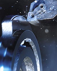
Interrupted cuts in turning direct all of the cutting forces toward a single point: the insert tip.
Tick, tick, tick, tick, tick. That’s the sound of an interrupted cut. Chances are that’s also the sound your turning insert makes as it chips, requiring you to stop the lathe for the fourth time in an hour to change tools.
Frequent interruptions to the machining process are a real pain in the neck. What can you do about them? Before answering that question, let’s first define “interrupted cut.”
While preparing this article, I looked for, but didn’t find, a definition in the metalcutting books I checked. I found some helpful information in several tool suppliers’ insert catalogs, but, as I will explain later, it seemed slightly ambiguous to me.
To keep things simple, let’s just say an interrupted cut is when the nonuniform shape of the workpiece disrupts the otherwise smooth removal of material.
Different Interruptions
Mill operators deal with interrupted cuts every day. But there are a couple of major differences between interrupted machining on a lathe and everyday machining on a machining center.
The first is the number of cutting edges that are in the cut at any given moment. During milling, the cutting tool usually has at least two edges in the cut at all times. With turning, there is never more than one. Consequently, in turning, all of the cutting forces are directed toward a single point: the insert tip.
Second, chip formation in milling is usually less abrupt than it is in turning. And depending on the entry angle of the cutting tool relative to the workpiece, milling generally places more of the initial shock behind the tool’s cutting edge, lessening the chance of it being damaged.
There are many different types of interrupted cuts, but they can be broken down into two basic groups. The first is encountered when roughing irregularly shaped workpieces such as castings and forgings. A tooling catalog would define these as “heavy” interruptions.
Rough turning a casting can be hard on inserts. But when the tool fails, it’s a simple matter to exchange it for a new one and continue machining, because tolerances are usually loose during a roughing operation. Depending on the shape, rough machining a casting is probably easier to do than finish machining a part that has had secondary operations performed on it, such as slot milling or the drilling of cross holes.
Finish turning an interrupted workpiece can be extremely difficult. When the cutting tool fails, replacement usually requires more than swapping out the old insert for a new one. A tight workpiece tolerance might require using the CNC’s wear-offset feature to back off the cutting tool, make a trial cut, measure and then take the finishing pass.
But depending on the nature of the interruption and the type of material, tool wear can occur so rapidly that you may only get a few cuts per insert. This can mean a continuous cycle of tool changes and offsets that leads to poor production and lots of scrapped parts.
What can you do when faced with such a situation? To answer that question, let’s look at some examples.
‘Character Builders’
Many years ago, I began working at a shop that routinely machined a variety of parts with interrupted cuts. Being the new guy, I usually ended up producing these parts. The foreman called them “character builders.”
One day he handed me a cardboard box containing a print, a paper tape, a process sheet, three sets of pie jaws and 50 cut blanks. (It was a very heavy box.)
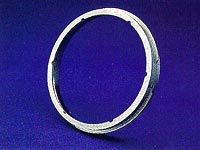
Figure 1: The biggest challenge of machining this heat-treated 17-4 PH stainless steel part involved facing the shoulders of the thin ring in the center. Tools consistently failed after only a few cuts.
The drawing was for a difficult little ring made out of 17-4 PH stainless steel (Figure 1). I can assure you I didn’t refer to it as a character builder as I walked back to my machine, struggling with the cardboard box.
I sat down and began studying the process sheet. The machining sequence consisted of rough turning and boring the blank, leaving 0.010″ to 0.015″ of stock. The part was then finish-milled and sent out to be heat-treated to a hardness of Rc 35.
Producing the part wasn’t terribly difficult by today’s standards. However, it did present some difficulties at the time, considering that the only tools I had available for the job were C-2 and C-5 brazed-carbide tools. These general-purpose, “soft” grades can hardly be considered “high-performance” tools for turning heat-treated stainless steel.
After heat treatment, the part was finish-turned. Some of the tolerances were as close as 0.0005″ on the diameters, with surface finishes down to 16 rms. Today, the part would be a good candidate for CNC cylindrical grinding, but CNC was still in its infancy back then, and the brains in the front office ruled out manual grinding as being “too slow.”
As it turned out, the majority of the work on the part was fairly easy. Turning the large diameters on either end was no great feat, and tool life was not an issue. The challenge came when I was facing the shoulders of the thin ring in the center of the part. No matter what I tried, tools failed after only a few cuts.
Following the carbide manufacturer’s recommendations for interrupted cutting, I began using a C-2 tool. I was turning at around 200 sfm. Since it appeared the tool was wearing, I reduced the cutting speed to 150 sfm. This didn’t help, either, so I lowered the speed to 100 sfm. Tool life decreased even further. After only one or two cuts, the tool would be shot.
For castings or forgings that involve heavy-interrupted cuts, use a low-to-moderate cutting speed and a tough, negative-rake tool.
Then I did the exact opposite of what my speed-and-feed slide rule told me to do. I replaced the tool with a harder grade of carbide (C-5) and increased the rpm. After adjusting the cutting parameters, I found the sweet spot for this job was at around 350 sfm and a feed rate of 0.002 ipr. Even though this was way beyond the manufacturer’s recommendation, it increased tool life to around 10 to 15 parts between sharpenings.
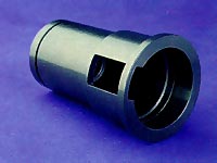
Figure 2: It may surprise some that interrupted cutting on aluminum can be problematic. With this part, interrupted cutting caused the aluminum to stick to the tool tip, creating build-up on the top face of the boring bar and smearing the bored finish.
My boss was so pleased with my success on this job that he gave me other character builders to work on. One of these was a 2024 aluminum part (Figure 2). Now, you might think that machining aluminum would not pose any tool-life problems, no matter how heavy the interrupted cuts were. And you’d be right.
But in this case, the problem was one of surface finish. I had to maintain a 16-rms finish throughout the bored area where the window cutout was. Using a brazed-carbide boring bar proved to be a bad idea, because the interrupted cutting made the aluminum stick to the tool tip, creating build-up on the top face of the boring bar and smearing the bored finish.
Increasing the speed helped, as did polishing the cutting edges with a hone. But it was only after convincing the shop foreman to spend $350 for an insertable boring bar and a diamond-tipped insert that the problem went away. The lubricious nature of the diamond insert solved the problem of the aluminum sticking to the cutting tool and marring the workpiece.
Since that time, I have also machined many different castings and forgings that involved heavy-interruption cuts. For these, the insert manufacturers’ recommendations were good ones: Use a low-to-moderate cutting speed and a tough, negative-rake tool. This combination makes short work of most heavily interrupted turning jobs.
Another common interrupted cut occurs when boring soft jaws—a challenge a lot of lathe operators face daily. This task is among the most difficult of all interrupted cutting, because the chuck jaws must be both accurate and smooth to ensure they precisely grip the workpiece. So, what makes jaw boring so difficult?
For starters, look at the profile of a typical soft jaw. Most chuck jaws have a slight relief at the bottom of the jaw profile, which eliminates the need to chamfer the workpiece blanks and allows the part to sit better in the jaws. To create this undercut, the machinist moves the boring tool in the X+ direction at the end of the boring pass—a cut that would usually call for a profiling insert.
However, many machinists take a shortcut and use this profiling insert for both roughing and finishing. How do you get a finish-grade profiling insert to hold up to the pounding of an interrupted cut? The answer, while not always satisfactory, is the same as for the stainless steel part mentioned earlier: Increase the surface footage, sometimes higher than the manufacturer’s specifications.
Making things even harder is that many machinists bore soft jaws manually. Rather than writing a program for the jaw-boring operation, they crank the MPG (manual pulse generator) by hand, running their $100,000 CNC lathe as though it were an engine lathe with an overpriced digital readout.
Avoid taking this shortcut. Cranking the handwheel manually results in inconsistent feed rates. It is also tough on cutting tools. Doing this can cause the boring insert to chip almost immediately.
Boring soft jaws is among the most difficult of all interrupted cutting, because the chuck jaws must be both accurate and smooth.
Additionally, many CNCs lose track of the cutting tool’s absolute position once the machinist switches to the manual mode. This means the operator will have to keep track of the tool position through the trial-and-error method of taking a cut, measuring the chuck jaws—sometimes a difficult chore in itself—adjusting the tool position, and so on. By writing a generic jaw-boring program and keeping it resident in the control at all times, the CNC lathe operator will save the company both time and money.
Another problem with interrupted cutting is thermal shock. During an interrupted cut, the temperature of the cutting tool cycles up and down rapidly as the insert moves in and out of the workpiece. This is especially true when running coolant. The best solution is to simply shut off the coolant.
But running dry usually means using a harder, more wear-resistant grade of carbide—just the opposite of what most manufacturers recommend for interrupted cuts. Sometimes, there is no good answer to this thorny problem.
A novice machinist working on his first interrupted-cutting job might assume that his insert is chipping. After all, it’s only logical that the shock of the cutting tool rapidly entering and exiting the cut would lead to chipping.
The novice’s reaction to seeing a chipped insert might be to try a tougher grade. For heavy interruptions, this would probably work, but sometimes the insert may appear to be chipping but isn’t. It might be built-up edge, particularly if it occurs during a finishing operation.
As mentioned earlier, cutting tool manufacturers are a little ambiguous when it comes to advice for interrupted cuts. On the one hand, they will tell you to use a softer grade of carbide to reduce chipping, then in the next breath they’ll tell you to increase the cutting speed to reduce BUE.
At times, the only solution is to grin and bear it—and keep a healthy supply of inserts on hand.
About the Author
Kip Hanson, a regular contributor to CTE, is general manager of Allen Co., Edina, Minn.
Use a box-way machine when possibleMachine tool construction can have a profound impact on the success or failure of any machining operation. This is especially true under difficult conditions, such as those found during interrupted cuts.
Linear-way machines are a poor choice for making parts with heavy interruptions. A machine with conventional box ways is a better choice.
However, CNC machines with box ways are becoming less common. Linear ways are cheaper to install and are usually more accurate, because there’s less friction between the way surfaces.
If you have a choice, try to do your heavy machining on a conventional-way machine. If you’re not sure which type of machine you have, take a look at the back of it. Linear-way machines have large bearing packs called trucks, which ride on rails between the machine axes and the ways.
—K. Hanson


MFGAxis Discussion