| Advanced cermet and ceramic boring tools are ready to take on the challenges of boring. |
| Every shop hopes to be the first to take advantage of a new process. It was this drive to be more productive than their competitors that inspired the industry’s pioneers to try carbide cutting tools when they were first introduced. Now, carbide has become the cutting tool material of choice for shops that want to produce quality parts faster and cheaper. |
Among shops that perform boring operations, carbide cutting tools have long been preferred for their performance in tough boring applications. But carbide may no longer be the optimal boring-tool material. For applications other than boring, shops have already discovered that they can cut metal more efficiently and less expensively with tools made of cermet and ceramic materials. Recent advances in these materials are making them viable alternatives to carbide for boring as well. Because boring must produce a precise cut and a fine finish in a confined space, it is a uniquely challenging operation. Cermet and ceramic boring tools possess the properties necessary to help meet these challenges.
Boring’s Challenges
Boring is a turning operation performed with a boring bar on the interior diameter of a part. Because the operation is inside the part, chips cannot drop freely away from the cutting area. If chip control is inadequate, stray chips can scar the walls of the part, build up around the holder, and fall back into the cutting area to be recut by the boring tool. A key point to remember is that because a boring bar is cutting parallel to the part centerline (as opposed to a turning tool, which cuts perpendicular to the part centerline), a right-hand boring bar uses left-hand inserts and a left-hand bar uses right-hand inserts. If the operator gets this reversed, he will be attempting to bore with the noncutting edge of the insert.
In addition to chip-control problems, a boring operation can be marred by inadequate attention to the project’s finish requirements and improper planning for these requirements. Planning is especially important when boring small-diameter parts. An operator who tries to hold a tight finish by taking a very fine finishing cut can create long, stringy, unmanageable chips. If the operator attempts to maintain a tight finish with a long tool overhang, chatter may result.
Boring operations can also be plagued by coolant-application problems. Applying coolant directly on the cutting point when it is deep inside the bore can be difficult. But if a good flow of coolant is not maintained, the resulting increase in tool pressure and temperatures and inadequate chip control can decrease tool life.
An Alternative to Carbide
It may not be possible to make boring less challenging, but the impact these difficult conditions have on tool performance will be much less if the operator bores with cermet or ceramic tools. These tools must be applied properly, however, to take advantage of their unique properties.
Cermets might be considered hybrid tools, combining the properties of ceramic and metallic materials (such as carbide). Cermets are composed of ceramic powders mixed with metal binders such as nickel, cobalt, and titanium nitrides for increased toughness. Cermets are manufactured through the same basic process as coated carbide tools; the powders are pressed into a mold, and then sintered into a solid tool under high pressure and heat. Although cermet and coated carbide tools are manufactured similarly, cermets offer superior wear resistance, longer tool life, higher cutting speeds, and superior surface finishes while costing less than coated carbide. Cermets’ combination of ceramic and metallic properties allows them to be used in a wide range of operations, including boring, turning, grooving, threading, and milling.
It is their ceramic properties that make it possible for cermet tools to produce superior surface finishes. By using cermet tools, shops can often meet finish requirements without secondary operations. The ceramic in the tool matrix makes the tool wear-resistant, and this wear resistance allows the operator to run the tool at much higher speeds than coated carbides without destroying the cutting edge prematurely. With higher speeds comes a finer finish. The cermet tool’s lower reactivity with steel also contributes to finer surface finishes. Steel adheres to the titanium carbide in cermet tools at a much higher temperature than it adheres to the tungsten carbide in carbide tools. As a result, chips do not stick to cermet tools as readily. With tungsten-carbide tools this accumulation on the cutting edge can damage the workpiece’s surface.
The cermet tool’s ceramic component also allows the tool to tolerate high temperatures. Because extreme heat does not damage the tool’s cutting edge, coolant is not required to carry the heat away. Thus, the coolant-application problems inherent in boring are eliminated. A flow of coolant may still be needed for chip control, however. The application of coolant was a problem with earlier cermets, which were damaged by thermal shock when the hot tool came in contact with the fluid. But new-generation cermets have the toughness to withstand these shocks.
To take advantage of cermets’ properties, users should run them at a higher speed than they run carbide boring tools. The increased sfm will result in lower machining costs through reduced machine times and improved surface finishes. The sfm for cermets is generally 20% to 30% faster than coated carbides in boring operations.
Boring operations typically range from finishing to semiroughing. These are operations for which cermet tools are ideally suited. A wide range of depths of cut (DOC) can be used with cermet boring tools, depending on the chipbreaker type, the size of the insert, and the material to be cut. Generally, the DOC for a cermet tool is less than the DOC that could be used with a carbide tool in the same material.
Chip control is still critical when boring with cermet tools. Users rely on the cermets’ chipbreakers to break chips and direct them safely away from the cutting area. Cermet-tool manufacturers offer a wide variety of chipbreaker designs ground or molded into the cermet insert. Ground chipbreakers can be especially useful when boring with cermets, because they produce lower tool pressure, produce a better surface finish, and are freer cutting than molded chipbreakers (Figure 1). Cermets with molded chipbreakers cost less than cermets with ground chipbreakers, but they produce higher tool pressure.Performance Enhancers
Coatings are another option that can enhance cermets’ performance in some situations. Most cermet inserts are not coated, and the absence of a coating gives the tools a sharper edge than carbide tools that have been coated using a chemical-vapor-deposition process. This sharper edge can be utilized in a broad range of materials that require a ground chipbreaker. But some applications may benefit from the toughness that can be gained through a cermet’s tougher substrate and the coating process. Cermets with ground or molded chipbreakers are coated with titanium nitride using a physical-vapor-deposition process. With the addition of molded chipbreakers, coated cermet tools can be used in applications ranging from fine finishing to roughing. The wide selection of molded chipbreakers makes it possible for the user to choose a tool specifically designed for the material being machined, whether the workpiece is carbon steel, alloy steel, stainless steel, cast iron, or an aerospace material.
The Case for Ceramics
The move from carbide to cermet boring tools may seem like a reasonable step for shops seeking a competitive advantage. But the logic behind a switch to ceramic tools may not be so obvious. When ceramics were first introduced, the general perception was that their hardness made them too brittle for general machining applications. The aluminum-oxide tools that were first on the market were generally used for the finish turning of gray and malleable cast irons. Through exhaustive R&D in the years since, manufacturers have greatly enhanced the performance of ceramic cutting tools. Today’s ceramic tools are widely accepted as viable alternatives to carbide tools. More advanced ceramics are even replacing cubic-boron-nitride (CBN) inserts. Ceramics can be used to bore carbon steel, alloy steel, aerospace material, or cast iron in operations ranging from fine finishing work to heavy roughing. On average, ceramics can bore at speeds 50% to 60% faster than carbides and 20% to 25% faster than cermets.
Ceramics are categorized as cold-press, hot-press, silicon-nitride, and whisker-reinforced. Cold-press ceramics, which are used for finishing cast irons and steels, are generally composed of various types of aluminum and zirconium oxides. These powders are then pressed into shape without any external heat prior to the firing process. Hot-press ceramics can include such materials as aluminum oxides and titanium carbides. These compounds are molded with external heat and high pressure to create tools for finishing steels and hard-turning parts. Silicon-nitride ceramics are similar to hot-press ceramics but possess the added silicon nitrides. They are generally used for roughing cast irons. Silicon-nitride and hot-press ceramics also have similar molding processes, but the pressures obtained in the firing process for silicon-nitride ceramics are much greater, thus giving them different cutting characteristics. Whisker-reinforced ceramics are the newest type of ceramic tool to enter the market. Unlike the other ceramic tools, these tools are laced with whiskers - or fibers - to give them increased toughness and wear resistance.
Ceramics are exceptionally hard materials - in fact, diamond and CBN are the only harder materials used for cutting tools. Consequently, a ceramic tool is extremely wear resistant when used in its proper application range at the appropriate speed, feed, DOC, and tool overhang. Because of ceramic tools’ outstanding wear resistance, users can significantly reduce their machining times by boring at extremely high speeds and feeds. Speeds for ceramics can range anywhere from 250 to 2,500 sfm, depending on the application.
As with cermets, users do not need to use coolant when boring with ceramic cutting tools. In fact, the thermal shock from contact with coolant could destroy a ceramic tool in some cases. However, certain types of ceramics can be run with coolant, so it is still possible to use ceramic tools even if coolant is needed for chip control, if the coolant cannot be turned off, or if coolant has built up in the bore due to previous operations. Silicon-nitride ceramics perform best in this type of environment.
Because ceramic inserts do not react with the work material and because they can bore workpieces at high speeds, the surface-finishing capabilities of ceramic boring tools are second to none. In some cases, ceramics can provide a surface finish as good as grinding can produce. The best surface finishes can be achieved when boring materials with a hardness above RC 45. However, a ceramic tool will produce a better finish than any other cutting tool material even when boring materials below RC 45 if proper chip control is used. Secondary operations, such as grinding, polishing, or reaming, are often unnecessary when ceramic boring tools are used.
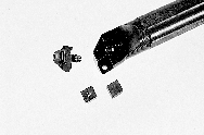 |
Figure 2: Ceramic inserts are mounted in boring bars with clamp-down mounting hardware such as this. |
Ceramics in Use
Chip control with ceramic boring tools differs somewhat from chip control with cermets. Ceramic inserts are generally flat topped with no molded or ground chipbreakers. Therefore, users employ mechanical chipbreakers when boring with ceramics. These chipbreakers are usually made of carbide and are installed between the insert and the clamp. The chipbreaker can be adjusted forward or back to accommodate different DOCs. With the addition of the chipbreaker, holders for ceramic inserts tend to be larger than those for carbide or cermet inserts. Ceramic inserts are generally held with a clamp-down style of toolholder rather than the screw-down system used with cermets or carbides (Figure 2). The clamping system adds height to the toolholders and thus decreases the minimum bore capabilities of these tools.
Remember the BasicsBecause ceramic inserts are not made with chipbreakers, the range of DOCs they can bore at depends on the insert’s edge preparation. Ceramic inserts have either a chamfered edge (T-land), a honed edge, or a combination of both (Figure 3). By strengthening the cutting edge, this chamfer or hone allows larger DOCs. The rule of thumb is that the DOC should equal or exceed the edge preparation. Generally, the edge preparation for boring inserts will be between 0.003" and 0.008" and 15° to 25°.
Although users can significantly improve productivity by boring with ceramic or cermet tools, they must still follow the general principles of the operation. A change to ceramic or cermet tools will have no effect on tool rigidity, which is related to the type of material the shank is made of (typically steel, carbide, or heavy metal) and the ratio of overhang length to the bar’s diameter (Figure 4). The operator will still have to maintain a proper overhang ratio to avoid tool chatter or breakage and to bore at productive speeds and feeds. The maximum overhang ratios for the most common boring bars are:
| Steel-shank bars | 3.5-to-1 |
| Heavy-metal-shank bars | 5.0-to-1 |
| Carbide-shank bars | 8.0-to-1 |
Applications for cermet and ceramic boring tools are increasing rapidly with the introduction of newer, more advanced materials. With their ability to produce finer finishes while boring at higher speeds with little or no coolant, ceramics and cermets can help shops meet their objectives whenever a job calls for faster cycle times, decreased downtime, and cost reductions.Another principle of boring that is frequently overlooked is the need to observe the boring bar’s minimum bore requirements (Figure 5). Minimum bores are specified for boring bars to ensure proper clearance for the tool. Also for clearance, the bars and the inserts require relief on their back sides. As a general rule, operators use positive-style boring inserts to help achieve the necessary clearance angles. If the tool is not relieved or is used in a hole that is too small, either the tool will not fit into the hole or the back side of the tool will rub on the wall of the bore. The size of the bore must be considered before the tool is chosen. If a tool that is too large is selected, and the operator is forced to remove material from the bar or insert to fit the tool into the bore, then the rigidity of the tool will be compromised and the operation will be more prone to problems.
About the Author
Brent Lindsey is an applications engineer at the Ceratip Technical Center, Kyocera Industrial Ceramics Corp., Mountain Home, NC.
Related Glossary Terms
- boring
boring
Enlarging a hole that already has been drilled or cored. Generally, it is an operation of truing the previously drilled hole with a single-point, lathe-type tool. Boring is essentially internal turning, in that usually a single-point cutting tool forms the internal shape. Some tools are available with two cutting edges to balance cutting forces.
- boring bar
boring bar
Essentially a cantilever beam that holds one or more cutting tools in position during a boring operation. Can be held stationary and moved axially while the workpiece revolves around it, or revolved and moved axially while the workpiece is held stationary, or a combination of these actions. Installed on milling, drilling and boring machines, as well as lathes and machining centers.
- cast irons
cast irons
Cast ferrous alloys containing carbon in excess of solubility in austenite that exists in the alloy at the eutectic temperature. Cast irons include gray cast iron, white cast iron, malleable cast iron and ductile, or nodular, cast iron. The word “cast” is often left out.
- ceramics
ceramics
Cutting tool materials based on aluminum oxide and silicon nitride. Ceramic tools can withstand higher cutting speeds than cemented carbide tools when machining hardened steels, cast irons and high-temperature alloys.
- cermets
cermets
Cutting tool materials based mostly on titanium carbonitride with nickel and/or cobalt binder. Cermets are characterized by high wear resistance due to their chemical and thermal stability. Cermets are able to hold a sharp edge at high cutting speeds and temperatures, which results in exceptional surface finish when machining most types of steels.
- chatter
chatter
Condition of vibration involving the machine, workpiece and cutting tool. Once this condition arises, it is often self-sustaining until the problem is corrected. Chatter can be identified when lines or grooves appear at regular intervals in the workpiece. These lines or grooves are caused by the teeth of the cutter as they vibrate in and out of the workpiece and their spacing depends on the frequency of vibration.
- chipbreaker
chipbreaker
Groove or other tool geometry that breaks chips into small fragments as they come off the workpiece. Designed to prevent chips from becoming so long that they are difficult to control, catch in turning parts and cause safety problems.
- clearance
clearance
Space provided behind a tool’s land or relief to prevent rubbing and subsequent premature deterioration of the tool. See land; relief.
- coolant
coolant
Fluid that reduces temperature buildup at the tool/workpiece interface during machining. Normally takes the form of a liquid such as soluble or chemical mixtures (semisynthetic, synthetic) but can be pressurized air or other gas. Because of water’s ability to absorb great quantities of heat, it is widely used as a coolant and vehicle for various cutting compounds, with the water-to-compound ratio varying with the machining task. See cutting fluid; semisynthetic cutting fluid; soluble-oil cutting fluid; synthetic cutting fluid.
- cubic boron nitride ( CBN)
cubic boron nitride ( CBN)
Crystal manufactured from boron nitride under high pressure and temperature. Used to cut hard-to-machine ferrous and nickel-base materials up to 70 HRC. Second hardest material after diamond. See superabrasive tools.
- edge preparation
edge preparation
Conditioning of the cutting edge, such as a honing or chamfering, to make it stronger and less susceptible to chipping. A chamfer is a bevel on the tool’s cutting edge; the angle is measured from the cutting face downward and generally varies from 25° to 45°. Honing is the process of rounding or blunting the cutting edge with abrasives, either manually or mechanically.
- feed
feed
Rate of change of position of the tool as a whole, relative to the workpiece while cutting.
- flat ( screw flat)
flat ( screw flat)
Flat surface machined into the shank of a cutting tool for enhanced holding of the tool.
- gang cutting ( milling)
gang cutting ( milling)
Machining with several cutters mounted on a single arbor, generally for simultaneous cutting.
- grinding
grinding
Machining operation in which material is removed from the workpiece by a powered abrasive wheel, stone, belt, paste, sheet, compound, slurry, etc. Takes various forms: surface grinding (creates flat and/or squared surfaces); cylindrical grinding (for external cylindrical and tapered shapes, fillets, undercuts, etc.); centerless grinding; chamfering; thread and form grinding; tool and cutter grinding; offhand grinding; lapping and polishing (grinding with extremely fine grits to create ultrasmooth surfaces); honing; and disc grinding.
- grooving
grooving
Machining grooves and shallow channels. Example: grooving ball-bearing raceways. Typically performed by tools that are capable of light cuts at high feed rates. Imparts high-quality finish.
- hardness
hardness
Hardness is a measure of the resistance of a material to surface indentation or abrasion. There is no absolute scale for hardness. In order to express hardness quantitatively, each type of test has its own scale, which defines hardness. Indentation hardness obtained through static methods is measured by Brinell, Rockwell, Vickers and Knoop tests. Hardness without indentation is measured by a dynamic method, known as the Scleroscope test.
- milling
milling
Machining operation in which metal or other material is removed by applying power to a rotating cutter. In vertical milling, the cutting tool is mounted vertically on the spindle. In horizontal milling, the cutting tool is mounted horizontally, either directly on the spindle or on an arbor. Horizontal milling is further broken down into conventional milling, where the cutter rotates opposite the direction of feed, or “up” into the workpiece; and climb milling, where the cutter rotates in the direction of feed, or “down” into the workpiece. Milling operations include plane or surface milling, endmilling, facemilling, angle milling, form milling and profiling.
- numerical control ( NC)
numerical control ( NC)
Any controlled equipment that allows an operator to program its movement by entering a series of coded numbers and symbols. See CNC, computer numerical control; DNC, direct numerical control.
- parallel
parallel
Strip or block of precision-ground stock used to elevate a workpiece, while keeping it parallel to the worktable, to prevent cutter/table contact.
- polishing
polishing
Abrasive process that improves surface finish and blends contours. Abrasive particles attached to a flexible backing abrade the workpiece.
- relief
relief
Space provided behind the cutting edges to prevent rubbing. Sometimes called primary relief. Secondary relief provides additional space behind primary relief. Relief on end teeth is axial relief; relief on side teeth is peripheral relief.
- shank
shank
Main body of a tool; the portion of a drill or similar end-held tool that fits into a collet, chuck or similar mounting device.
- threading
threading
Process of both external (e.g., thread milling) and internal (e.g., tapping, thread milling) cutting, turning and rolling of threads into particular material. Standardized specifications are available to determine the desired results of the threading process. Numerous thread-series designations are written for specific applications. Threading often is performed on a lathe. Specifications such as thread height are critical in determining the strength of the threads. The material used is taken into consideration in determining the expected results of any particular application for that threaded piece. In external threading, a calculated depth is required as well as a particular angle to the cut. To perform internal threading, the exact diameter to bore the hole is critical before threading. The threads are distinguished from one another by the amount of tolerance and/or allowance that is specified. See turning.
- titanium carbide ( TiC)
titanium carbide ( TiC)
Extremely hard material added to tungsten carbide to reduce cratering and built-up edge. Also used as a tool coating. See coated tools.
- titanium nitride ( TiN)
titanium nitride ( TiN)
Added to titanium-carbide tooling to permit machining of hard metals at high speeds. Also used as a tool coating. See coated tools.
- toolholder
toolholder
Secures a cutting tool during a machining operation. Basic types include block, cartridge, chuck, collet, fixed, modular, quick-change and rotating.
- tungsten carbide ( WC)
tungsten carbide ( WC)
Intermetallic compound consisting of equal parts, by atomic weight, of tungsten and carbon. Sometimes tungsten carbide is used in reference to the cemented tungsten carbide material with cobalt added and/or with titanium carbide or tantalum carbide added. Thus, the tungsten carbide may be used to refer to pure tungsten carbide as well as co-bonded tungsten carbide, which may or may not contain added titanium carbide and/or tantalum carbide.
- turning
turning
Workpiece is held in a chuck, mounted on a face plate or secured between centers and rotated while a cutting tool, normally a single-point tool, is fed into it along its periphery or across its end or face. Takes the form of straight turning (cutting along the periphery of the workpiece); taper turning (creating a taper); step turning (turning different-size diameters on the same work); chamfering (beveling an edge or shoulder); facing (cutting on an end); turning threads (usually external but can be internal); roughing (high-volume metal removal); and finishing (final light cuts). Performed on lathes, turning centers, chucking machines, automatic screw machines and similar machines.
- wear resistance
wear resistance
Ability of the tool to withstand stresses that cause it to wear during cutting; an attribute linked to alloy composition, base material, thermal conditions, type of tooling and operation and other variables.