Whether a railway carriage carries freight or passengers over the 225,308 km (140,000 miles) of track in the U.S. railway network, wheel sets wear out and must be re-profiled or scrapped when outside the tolerances set by the Association of American Railroads. Since 1910, Simmons Machine Tool Corp., Albany, New York, has built machine tools and measuring machines for producing and maintaining railway wheel sets. The company also manufactures automation systems.
When worn wheel sets arrive at an AAR-certified railway wheel maintenance facility, the end caps and bearings first are removed and manually inspected. The serial numbers for each wheel set component then are entered into a supervisory control and data acquisition system. A measurement machine qualifies the parameters of a worn wheel set. Based on that data, a wheel set is either re-profiled on a machining center or scrapped.

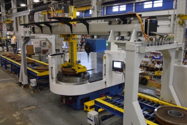
Simmons Machine Tool chose the ZP-6 overhead gantry with a two-axis robot to provide most of the material-handling capability for the Wheel Turning Center, a vertical CNC lathe for machining railway wheels. Image courtesy of Güdel
Each wheel traditionally is placed on a machining center using a forklift, a crane or another manual handling method — a slow, inconsistent process in which worker safety is a concern. When workers place hooks around a wheel to lift it, there are potential pinch points, so personnel risk suffering from repetitive motion injuries or even having hands crushed under the wheel, said Scott Mitchell, manager of turnkey projects at Simmons Machine Tool.
“All those things are there because the operator has to manually move the wheel,” he said.
When the machine builder designed its new Wheel Turning Center, a vertical CNC lathe for machining railway wheels, its goals were to maximize worker safety and boost productivity to avoid repair delays. For the WTC-60 model, Simmons automated most of the process to avoid making operators manually handle wheels. For the automation system, the company turned to Coventry, U.K.-based Güdel Lineartec U.K. Ltd., which Simmons Machine Tool has worked with for about 30 years. (Güdel Inc. is in Ann Arbor, Michigan.)
Although Simmons Machine Tool historically has had success with Güdel, Mitchell said Simmons Machine Tool explores the market every five or six years to “see if Güdel is still all that we need.”
Those searches include Simmons Machine Tool’s sister company that manufactures components for automation systems.
For the WTC-60, Simmons Machine Tool selected Güdel’s ZP-6 double-axis gantry robot.
“Simmons chose Güdel’s ZP-6 gantry system for this application primarily for its reliability and capability and because equipment availability is critical for our customers,” said Jason Steven Murphy, marketing specialist at Simmons.
Mitchell said the ZP-6 gantry is probably the lowest-cost option that still provides the throughput that customers need. The complete machine cell, however, stands about 4.5 m (14.8') high. If a customer’s facility cannot accommodate that height, Simmons Machine Tool offers other automation options, such as a six-axis robot.
When designing the WTC-60, the company modified a “widely available, generic” vertical turning center by adding a special table and tooling, reinforcing the column and enhancing the guarding, he said.

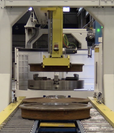
Wheel sets that require machining are placed onto a conveyor and transported into a machine cell. To accomplish this task, each wheel is picked up by a vertical lift system from Güdel. Image courtesy of Güdel
Nonetheless, Mitchell said, Simmons didn’t build the base machine, and the cell didn’t supply the rigidity required for the freight side of the industry, which moves heavier loads than the transit side.
“It is not a machine we would offer across the board,” he said.
When reviewing the designs of Simmons Machine Tool’s older machines, which can last 40 years or more, the company chose to return to a moving-column design for the latest WTC-250 model.
“We found there was this love for the moving-column design,” Mitchell said.
He said that design allows the mass of the machine carrying the cutting tools, or its center of gravity, to move over the top of a wheel, increasing stiffness.
“That means you can take deeper cuts and beat the machine up way more than the WTC-60,” Mitchell said.
In addition to building the vertical CNC lathe for the WTC-250, Simmons Machine Tool designed and produced special grippers to handle the heavy wheels, which use a V-shaped roller and the wheel flange as a gripping area.
“We are able to center the wheel that way because we have four different contact points,” Mitchell said. “If we can grab the flange, we know we are repeatedly locating the wheel.”
The system transfers a wheel to the machine, which bores the center hole of the wheel. It then is placed by Güdel’s gantry on an outbound conveyor for pressing onto an axle. He estimates that about 90% of wheels require only boring of their center holes, but others with a drive system or that have disc brakes mounted to them need additional machined features, such as drilled and threaded holes. For those applications, Simmons Machine Tool offers the WTC-250 mc, which is short for machining center.
The company says access to pre- and post-machining measurement data is important to railway companies so they can extend the lives of wheels, as well as maintenance machines and automation systems.
“The more data you can provide to them, the more excited they get,” Mitchell said.
The interest in data began when sensors were added to locomotives to provide feedback about their performance.
“That culture shift has taken a few years,” Mitchell said. “But now everybody is asking the question, ‘How do I get more data on the rest of it?’”
For more information about wheel boring by Simmons Machine Tool, view a video presentation at www.ctemag.com by scanning the QR code on your smartphone or entering this URL on your web browser: cteplus.delivr.com/22urr
Related Glossary Terms
- arbor
arbor
Shaft used for rotary support in machining applications. In grinding, the spindle for mounting the wheel; in milling and other cutting operations, the shaft for mounting the cutter.
- boring
boring
Enlarging a hole that already has been drilled or cored. Generally, it is an operation of truing the previously drilled hole with a single-point, lathe-type tool. Boring is essentially internal turning, in that usually a single-point cutting tool forms the internal shape. Some tools are available with two cutting edges to balance cutting forces.
- computer numerical control ( CNC)
computer numerical control ( CNC)
Microprocessor-based controller dedicated to a machine tool that permits the creation or modification of parts. Programmed numerical control activates the machine’s servos and spindle drives and controls the various machining operations. See DNC, direct numerical control; NC, numerical control.
- gantry robot
gantry robot
Robot positioned by means of an overhead supporting structure such as a crane or bridge-type support.
- lathe
lathe
Turning machine capable of sawing, milling, grinding, gear-cutting, drilling, reaming, boring, threading, facing, chamfering, grooving, knurling, spinning, parting, necking, taper-cutting, and cam- and eccentric-cutting, as well as step- and straight-turning. Comes in a variety of forms, ranging from manual to semiautomatic to fully automatic, with major types being engine lathes, turning and contouring lathes, turret lathes and numerical-control lathes. The engine lathe consists of a headstock and spindle, tailstock, bed, carriage (complete with apron) and cross slides. Features include gear- (speed) and feed-selector levers, toolpost, compound rest, lead screw and reversing lead screw, threading dial and rapid-traverse lever. Special lathe types include through-the-spindle, camshaft and crankshaft, brake drum and rotor, spinning and gun-barrel machines. Toolroom and bench lathes are used for precision work; the former for tool-and-die work and similar tasks, the latter for small workpieces (instruments, watches), normally without a power feed. Models are typically designated according to their “swing,” or the largest-diameter workpiece that can be rotated; bed length, or the distance between centers; and horsepower generated. See turning machine.
- machining center
machining center
CNC machine tool capable of drilling, reaming, tapping, milling and boring. Normally comes with an automatic toolchanger. See automatic toolchanger.
- stiffness
stiffness
1. Ability of a material or part to resist elastic deflection. 2. The rate of stress with respect to strain; the greater the stress required to produce a given strain, the stiffer the material is said to be. See dynamic stiffness; static stiffness.
- turning
turning
Workpiece is held in a chuck, mounted on a face plate or secured between centers and rotated while a cutting tool, normally a single-point tool, is fed into it along its periphery or across its end or face. Takes the form of straight turning (cutting along the periphery of the workpiece); taper turning (creating a taper); step turning (turning different-size diameters on the same work); chamfering (beveling an edge or shoulder); facing (cutting on an end); turning threads (usually external but can be internal); roughing (high-volume metal removal); and finishing (final light cuts). Performed on lathes, turning centers, chucking machines, automatic screw machines and similar machines.
- web
web
On a rotating tool, the portion of the tool body that joins the lands. Web is thicker at the shank end, relative to the point end, providing maximum torsional strength.
- wheel flange
wheel flange
Metal plate inside the grinding-wheel hole that allows the wheel to be mounted on a spindle.
End User
Simmons Machine Tool Corp., 518-462-5431, www.smtgroup.com
Solution Provider
Güdel Inc., 734-214-0000, www.us.gudel.com
Challenge
Boost productivity and improve worker safety when loading and unloading railways for repairs in a vertical CNC lathe.
Solution
Automated material handling through use of a double-axis gantry robot with special grippers.


