A high-performance machining center requires more than just a high-speed spindle.
What’s the difference between a high-performance machining center and a high-speed machining center? A high-speed machine features a high-speed spindle. Period. A high-performance machine features many critical components, ranging from basic design elements such as axis guide ways, ballscrews, and servodrives to advanced spindle and spindle-motor technology. Also included are CNC controls and software that allow the machine to perform efficiently at the higher feed rates necessary for truly successful high-speed machining.
Linear Motion Guides
The speed and accuracy of axis movements are crucial for high-speed machining. Regardless of spindle speeds and tooling technology, if the machine axis cannot move at ultra-high contouring feed rates (300 to 450 ipm) with the accuracy required for the job, then the operation is destined for failure.
Linear motion guide technology is being used more than ever for machine tool applications, especially for high-performance machining. Conventional box way designs are not capable of obtaining the speeds and accuracies of linear motion guide way designs. Linear motion guides’ coefficient of friction is approximately 1/20 that of box ways, because in linear guides there is less contact area between the ball bearings and the steel ways. As a result, linear guide ways consume 1/20 of the power that box ways do and are subject to less wear, lengthening machine life. Linear motion guides can be moved more quickly and accurately than conventional ways.
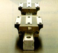
Figure 1: Linear motion guide ways have hardened and ground steel rails, precision steel bearings, and sliding trucks.
Precision linear motion guide ways are composed of steel rails that are hardened to approximately Rc 58-62 and then precision ground. Some rails have a single groove, but the most widely used rails in the machine tool industry have two grooves. The trucks also are made of hardened and ground material with grooves identical to those on the rails. The trucks are assembled and precision measured to determine the proper size of the steel ball bearings required to obtain the desired accuracy, preload, and stiffness (Figure 1).
How do linear motion guides obtain high accuracy? Let’s discuss the issue of friction. When the servomotor receives a command to move an axis, it must build up enough force to overcome the friction holding the axis in place. Once it overcomes the friction, the machine begins to move. Since a box way has more friction than a linear motion guide, it takes more force to move the machine on a box way.
There are two problems associated with the greater force required to move the machine. One problem is the higher cost of the larger servomotor that is needed to move the machine. The other problem is that there is more intense “stick-slip,” which occurs when force is applied to the axis to make a small movement. Initially, the axis resists. As the force increases and the static friction is overcome, the slide breaks free and moves forward.
The amount of energy required to break free of the initial friction is different from that required to keep the axis moving. Therefore, on small axis movements, the servomotor doesn’t react fast enough in regards to the amount of power being applied, and the axis overshoots its target, causing accuracy problems. Any time the machine must stop to change directions, this effect can occur. During a series of small movements, stick-slip could occur on all movements, creating a less accurate workpiece.
The stick-slip effect is greatly reduced on a machine with linear guides, because the difference between the static and kinetic friction coefficients is much smaller than that for a machine with box ways. For example, a machine with box ways may require 2,500 ft.-lb. of energy to break free of the static friction and 750 ft.-lb. of energy to overcome the kinetic friction. A machine with linear guides may require 1,200 ft.-lb. to overcome the static friction and 500 ft.-lb. to overcome the kinetic friction. The smaller difference results in less severe stick-slip.
How do linear motion guides achieve high speeds? While linear guides are capable of speeds up to 2,500 ipm, 1,500 ipm seems to be the current limit for practical machine tool applications. Any type of guide-way design is capable of 1,500 ipm, using a servomotor with enough power and a ballscrew large enough to withstand the force being applied to it. But, unlike box ways, linear guides can achieve this speed without high power requirements or unreasonable wear. Linear guides allow for higher rapid traverse rates and faster axis acceleration and deceleration.
Precision linear motion guides allow for feed rates of up to 1500 ipm, depending on the application. Since there is much less friction associated with linear guides, wear is greatly reduced and guide way life is significantly lengthened.
Another benefit of linear guides in regard to high-speed machining is machine stiffness and rigidity. The base must very stable and very heavy to support the other components moving at extremely high feed rates, with accelerations in the range of 0.6 to 1.0G. In addition to rigidity, the base must have a symmetrical design and fast and easy leveling capabilities.
Provided the guides are applied correctly, a machine with linear guides is much stiffer than one with box ways because there is no clearance between the mating surfaces of moving members. Box way systems have clearance that allows oil or air to be induced between the moving members. Due to this clearance, the system is less stiff, which can result in harmonic distortion or chatter under poor cutting conditions. Box ways have good damping characteristics at low spindle speeds and feed rates; however, running at these low speeds isn’t efficient using today’s tooling, spindle designs, and controls.
The “zero clearance” on linear guides also provides a fixed preload, since the load is the same everywhere on the guide way. This fixed preload allows less unwanted movement (pitch, yaw, roll) along the programmed axis, so positioning is more accurate.
Rigidity is also provided by the elastic displacement of the ball bearings in linear guides. In the event of a crash, the ball bearings actually deform or compress on impact but immediately spring back as the pressure is released. This allows them to handle heavy-impact loads very well.
Due to the tremendous stiffness of linear guides, there are fewer vibrations induced in the machine tool and machining process. This results in a better surface finish on the workpiece. In addition, fewer vibrations are transmitted through the tool itself, resulting in longer tool life. Actual improvements in tool life will vary depending on the application and the types of tools used.
Since linear guides generate less heat, there is less distortion due to thermal expansion. There is also less force applied to the ballscrew in order to move any given axis, which further reduces the generation of heat and improves machining accuracy.
Precision Ballscrews
The size and pitch of a machine tool’s ballscrews have a direct effect on accuracy, especially at high feed rates. The ballscrew can be one of the major areas of wear on a machine tool. Some of this wear is due to the heat generated by the mating surfaces. Due to the higher power requirements of a machine with box ways, as discussed earlier, it needs a larger ballscrew than a machine with linear guides does. The larger the ballscrew, the greater the contact area of the mating surfaces, thereby generating more heat, which in turn causes more wear and thermal distortion.
The finer the pitch of a ballscrew, the more accurately the ballscrew can position the axis slide. The problem with using a fine-pitch ballscrew for accuracy, however, is that a fine-pitch ballscrew must rotate much faster than a coarser-pitch ballscrew to obtain higher feed rates. For example, a ballscrew with a 0.500" pitch would move the slide 0.500" for every rotation of the ballscrew. To achieve a rate of 1,500 ipm on a guide way, that ballscrew would have to rotate at 3,000 rpm, which is extremely fast for a ballscrew.
However, using a ballscrew with a coarser pitch that doesn’t have to rotate at such a high rpm will reduce accuracy. The solution is to use a fine-pitch ballscrew that is of sufficient size and quality to withstand the force applied when rotating at high speeds.
Some machines are now being introduced with multilead ballscrews with a coarser pitch. The idea is to obtain higher feed rates and axis acceleration without sacrificing quality. However, these machines are fairly new, so final results are not yet known.
Another issue is whether the servomotor is directly coupled to the ballscrew or is connected by gears or pulleys. Directly coupling the servomotor to the ballscrew ensures that one revolution of the motor results in one revolution of the ballscrew. Using gears allows backlash, and using belts may cause slippage or inaccuracy due to belt wear or stretching.
A final consideration is the relationship of the ballscrew to the guide ways. As the servomotor is building up the energy needed to move the axis, all that energy is being applied to the ballscrew until the friction in the guide ways is overcome. Since a linear motion guide has less friction than a box way, less stress is placed on the ballscrew. Since there is less force being applied to it, the ballscrew doesn’t have to twist and flex as much, so it has a longer life. In addition, the ballscrew responds better to servo commands, improving machine accuracy.

Figure 2: Considerations for components of high-speed spindles.
While these issues apply to any machine tool, their importance is magnified under high-speed conditions. Machine accuracy and longevity may be compromised if all components are not used properly. There are many elements to consider just in the design of the high-speed spindle itself (Figure 2).
Spindle Horsepower
Among the factors that affect the amount of spindle horsepower required for a particular job are spindle taper, metal-removal requirements, part sizes, and tooling diameters. Larger spindle tapers can physically withstand higher-horsepower cuts. It doesn’t make sense to have a 50-hp motor on a 40-taper spindle, since a 50-hp cut would probably pull the tool out of the spindle. However, higher-horsepower motors are sometimes used on smaller spindles for faster accelerations and decelerations.
For high metal-removal requirements, a large spindle taper and a high-horsepower motor are required. Not as much horsepower is needed when working with castings or forgings, but high rpm may be desirable. On large workpieces, more horsepower is required to drive larger-diameter tools.
Spindle Bearings
The size and type of spindle bearings must be matched to the application for which they will be used. Larger-diameter bearings provide greater strength and rigidity. However, the larger size of the bearings and the spindle itself have two drawbacks. First, more heat will be generated due to the larger contact area of the bearings and the larger mass. This heat eventually will lead to spindle growth. Second, the larger mass will require more power to rotate the spindle itself. Even though the races are oiled, the bearings load up at high rpm and create a large mass that has to be turned. This means that a higher-horsepower motor must be used just to turn the spindle.
Figure 3: Horsepower consumption on a 30-hp spindle.
Figure 4: Horsepower availability on a 30-hp spindle.
Typically, as spindle rpm increases, horsepower consumption also increases (Figure 3). However, just because a spindle has a lot of horsepower doesn’t mean that all of it is available for machining (Figure 4). For example, a 40-hp spindle may have only 15 to 20 usable horsepower at the tool tip, since some horsepower is used just to turn the spindle. For a spindle to be most efficient, it should be able to deliver as much horsepower to the tool as possible. It should also use a minimum amount of horsepower to run at maximum rpm. To determine how much horsepower is being used, the load on the spindle should be checked at maximum rpm without a tool in the spindle. (Some manufacturers require a tool in the spindle to operate it at high speeds, because the clamp or retention system holding the tool might hang free or be unbalanced with no tool in place.)
It may be advantageous to use multiple sets of smaller-diameter bearings rather than one large set. With smaller-diameter bearings, the spindle itself will be smaller in diameter, so there will be less mass, less heat, and better use of spindle horsepower. By using multiple sets of bearings, spindle rigidity is not compromised.
Multiple sets of bearings also are beneficial in terms of preload. Bearing preload is the amount of pressure applied to the bearings when the spindle is in a static state. A higher spindle preload improves stiffness and cutting capabilities, but it also can increase bearing wear due to heat. Using multiple sets of bearings at a lower preload will provide the stiffness necessary for improved cutting capabilities and will extend bearing life due to the generation of less heat.
While demand for magnetic, air, and fluid bearings may increase in the long term, two types of bearings are currently used in most high-speed spindles—angular contact bearings and roller bearings. The most common arrangement for standard-rpm spindles is to use both roller bearings and angular contact bearings at the front of the spindle and roller bearings at the rear. Roller bearings are used at the front of the spindle because of their improved stiffness and side-milling capabilities, which are important for heavier cuts. However, since roller bearings have more contact area and mass than angular contact bearings, they require more horsepower and generate more heat, resulting in lower horsepower utilization and increased spindle growth. High-speed machining subjects the spindle and tool to lower radial loads, so angular contact bearings at the front of the spindle provide sufficient stiffness and rigidity, while reducing the risk of spindle growth occurring near the tool and the workpiece.
The bearing material is just as important as the bearing type. Although steel bearings are the most widely used in spindles today, there are many advantages to using ceramic bearings for high-speed machining applications. Steel bearings may be less expensive, but they have a greater weight than comparably sized ceramic bearings. Since they have more weight, steel bearings generate more heat, requiring the use of a more elaborate type of spindle cooling system. Also, as the rpm increases, the centrifugal force being applied to steel bearings is higher, increasing growth due to heat. This, in turn, leads to greater horsepower requirements.
Since ceramic bearings are lighter, they suffer less thermal expansion. Tests have shown that ceramic bearings grow at 1/4 the rate of steel bearings. Because ceramic bearings have less centrifugal force being applied to them at high rpm, they can use a higher preload, which improves the spindle stiffness and cutting capabilities.
Figure 5: Ceramic vs. steel bearing life.
All of these features of ceramic bearings translate into longer bearing life. Figure 5 compares the life of steel and ceramic bearings tested under identical conditions.
Current spindle technology allows the machine to adjust the preload on the bearings, depending on the spindle rpm. As spindle rpm increases, the load on the bearings increases due to the centrifugal force. Reducing the spindle preload at higher rpm reduces the load on the bearings and thereby decreases bearing growth due to heat.
A lower bearing preload can be used at higher rpm because the force being applied to the tool itself is lower at higher rpm, so not as much rigidity is needed. At lower rpm, a higher preload on the bearings is required, since the forces being applied to the spindle are higher due to increased tool load.
Spindle Motors and Drives
There are two ways to connect the spindle motor to the spindle itself. One method is to use belts or gears between the spindle motor and the spindle. The other is the direct drive method, where the spindle motor is directly coupled to the spindle or the spindle and spindle motor are combined into one complete unit called an integral spindle.
The advantage of using belts or gears is that the spindle motor can rotate at a slower speed and still generate high rpm at the spindle. This type of motor is less expensive due to its lower maximum rpm and power output.
However, there are several disadvantages associated with this design. There are more components, so the possibility of component failure is greater. Also, there is more vibration associated with a belt- or gear-driven spindle than with a direct-drive spindle. This vibration can be transmitted through the tool into the workpiece itself and result in a poor surface finish and shorter tool life.
Surface-finish tests were conducted on parts produced by two horizontal machining centers—one with a 2-range, 7,000-rpm gear-driven spindle, and one with a 1-range, 10,000-rpm integral direct-drive spindle. Under the same conditions, the integral spindle produced a better surface finish (Rmax = 2.7µm) than the gear-driven spindle (Rmax = 4.3µm).
Direct-drive spindles have proven to be more reliable simply because they have fewer moving parts. With an integral spindle, the total number of parts in the spindle itself is further reduced. Since the motor is directly coupled to the spindle, a direct-drive spindle accelerates and decelerates faster than a belt- or gear-driven spindle, and it doesn’t have to go through any drive-train mechanism.
Some spindles are composed of a separate spindle cartridge, motor, and gears or pulleys. Each component is of a different material and mass and, therefore, may have a different growth rate due to heat. This uneven thermal growth may distort the spindle along its axis, which can have a negative effect on the spindle’s accuracy. An integral spindle has a symmetrical growth rate, since the spindle and motor are in-line.
In addition, through-spindle coolant can be used with integral spindles, even at ultra-high spindle speeds. The older, cartridge-type spindles didn’t have this feature.
Cooling and Lubrication
Regardless of which type of cooling and lubrication system is used, all spindles suffer thermal expansion. To have a truly accurate spindle, the key is to control and stabilize spindle and bearing growth.
Some systems cool the outside of the spindle bearings, some cool the inside, and some do both. The preferred method for cooling the spindle bearings depends on the intended use of the spindle; however, external cooling is generally preferred over internal cooling. Heat from the spindle can be exhausted to the outside air to further facilitate cooling.
Ceramic bearings require less cooling than steel bearings of comparable size. A large-diameter spindle with roller bearings may need both internal and external cooling to handle the increased heat generated due to the larger size and bearing contact areas.
For the most efficient use of spindle horsepower, an oil mist or oil/air spindle-cooling system is recommended. Whether or not this type of system can be used on a high-speed spindle depends primarily on the spindle rpm and the bearing material. Spindle bearings have a DNN rating, equal to the maximum rpm of the spindle multiplied by the outer diameter of the bearings, that dictates the type of cooling system required (D=diameter, N=ID, N=rpm). If two spindles are identical except for bearing material, the spindle with ceramic bearings may be able to use an oil mist system, while the spindle with steel bearings may require an oil jet system, which provides a higher volume of coolant/lubricant but also may consume more horsepower.
Tooling Connection
Figure 6: HSK toolholder.
Although CAT V-flange is the most widely used spindle connection in use today, it appears that the newer hollow-shank, short-taper design known as HSK may become the preferred connection (Figure 6). Although the tooling available is limited and costly, HSK offers unmatched stability and accuracy at high rpm. These toolholders are machined to tight tolerances, with full contact along the taper and face. Compared to conventional toolholders such as CAT V-flange, HSK toolholders are lighter in weight, deliver lower radial runout and greater radial repeatability, and allow shorter changeover times.
The type of toolholder preferred for high-speed machining depends on the spindle rpm, the spindle taper, and the operations being performed. On a 10,000-rpm, 40-taper spindle, a prebalanced toolholder is acceptable. However, on a 25,000-rpm, 40-taper spindle, a balanceable toolholder is preferred, since it can be more precisely balanced. Sometimes it comes down to the expense of prebalanced vs. balanceable holders and the cost savings resulting from longer tool life.
If a tool is balanced well, it will last longer and can help improve the surface finish of the part. On higher-rpm spindles (20,000 to 40,000 rpm), good tool balancing has a positive effect on the life of the spindle bearings.
A single-plane tool balancer is sufficient for most applications of high-speed spindles. A two-plane balancer is useful on tools that are longer or have extended noses for reaching down into a part. The tool can be balanced at the base of the toolholder closer to the gage line, as well as out on the end of the holder.
CNC Controls
Current CNC technology allows a machine tool to machine parts at feed rates of more than 1,500 ipm. The higher surface speeds of cutting tools allow machines to be run at much higher feed rates. Doing this accurately requires servomotors that are capable of high rpm as well as fine resolution. In addition to providing better accuracy, a high-resolution motor also must be able to handle signals at a faster rate. For example, a motor capable of 5,000 pulses per second is not as accurate as one capable of 25,000 pulses per second. On a high-resolution motor, many more pulses must be sent to the motor to move a given distance along the axis. This is especially true for submicron motors, which move in increments of less than 1µm. Motors with a resolution of 0.5µm are currently available. For each pulse this type of motor receives, the axis will move 0.5µm.
Using a high-resolution motor without increasing the speed of the processor is senseless. Since a high-resolution motor requires a greater amount of data than its predecessors, faster block processing speeds are needed to process the data and send it to the motor. Dual 32-bit processors are required to handle the large amount of data and calculations associated with high-speed machining.
When machining large aerospace parts or mold parts, the part program may have to be fed to the machine from an external source, since the control memory may not be able to store all the data. Luckily, there are controls available that can handle data transfer rates as high as 76,800 characters per second, which is fast enough for the most demanding application.
Software has been developed that allows faster cutting feeds and improved machine accuracy. Depending on the requirements of the application, this software may be used to obtain a more accurate part at the same feed or to maintain part accuracy at a higher feed.
Figure 7: High-speed software helped provide a better surface finish on an aircraft component.
High-speed software allows machining of curved surfaces at up to 1,300 ipm. Three-dimensional parts such as molds and aerospace components can be machined in far less time than previously was possible. This software technology also can be used to improve the surface finish of a part with no increase in cycle time, as shown by the aircraft component test results in Figure 7. The ability to run at higher feed rates and maintain reasonable accuracies allows finer increments to be used in part programs. More passes on a part may be taken to improve the surface finish, without increasing cycle time. This is very important when machining molds or airfoil aerospace parts.
Not all high-speed machining involves ultra-high feed rates. To produce parts with tight tolerances, high-speed machining may mean cutting at feed rates of only 150 to 300 ipm, which is still fast by today’s standards.
Geometry-compensation software has been developed to improve part accuracy while allowing the user to cut at the same programmed feed rate that he was using previously. This software also will maintain part accuracy at a higher feed rate, again reducing cycle times.
Geometry-compensation software is different from the high-speed software discussed earlier. High-speed software will not improve part accuracy; it is used to increase feed rates, improve surface finishes, or reduce cycle time on three-dimensional parts.
The geometry-compensation function has four features:
Pre-interpolation acceleration/deceleration. In a circular interpolation movement, for example, there is inaccuracy between the programmed coordinates and the actual workpiece. This is caused by the delay in acceleration or deceleration of the axis as compared to the commanded value. The pre-interpolation acceleration/deceleration feature compensates for the error caused by this delay, thereby improving the accuracy of the workpiece.
Feed-forward control. Inaccuracy also can be caused by following error of the servo system itself. The feed-forward control feature looks ahead at the programmed path and feed rate and calculates the amount of error that will occur. It then can compensate for the error before it actually occurs. The amount of correction is controlled by the percentage of gain that is set in the machine parameters for each axis.
Precise vector compensation. When machining at high feed rates, the machine can be tuned to run optimally at a certain feed. This is done by adjusting the gain settings for the servomotors. When the feed-forward gain is set to a high value to improve error tracking, the servo system may be less stable, which can result in a poorer surface finish on the workpiece. The precise vector compensation feature “smooths” the programmed path on large, fine-increment part programs. This helps stabilize the feed system, thereby eliminating the vibration that can cause poor surface finishes.
Optimum corner deceleration. Even when using the previous three features, it sometimes is necessary to decelerate an axis to prevent any shock or vibration to the drive system. The optimum corner deceleration feature enables an axis drive to decelerate the proper amount at the proper time, which allows for a more accurate workpiece.
By incorporating the proper CNC, guide way, spindle, lubrication, and toolholding technologies, today’s machining centers can achieve consistently higher levels of accuracy and efficiency than previously were possible.
About the Author
Joe Kraemer is product manager, Machining Centers & Systems, at Mazak Corp., Florence, KY.
Related Glossary Terms
- backlash
backlash
Reaction in dynamic motion systems where potential energy that was created while the object was in motion is released when the object stops. Release of this potential energy or inertia causes the device to quickly snap backward relative to the last direction of motion. Backlash can cause a system’s final resting position to be different from what was intended and from where the control system intended to stop the device.
- centers
centers
Cone-shaped pins that support a workpiece by one or two ends during machining. The centers fit into holes drilled in the workpiece ends. Centers that turn with the workpiece are called “live” centers; those that do not are called “dead” centers.
- chatter
chatter
Condition of vibration involving the machine, workpiece and cutting tool. Once this condition arises, it is often self-sustaining until the problem is corrected. Chatter can be identified when lines or grooves appear at regular intervals in the workpiece. These lines or grooves are caused by the teeth of the cutter as they vibrate in and out of the workpiece and their spacing depends on the frequency of vibration.
- clearance
clearance
Space provided behind a tool’s land or relief to prevent rubbing and subsequent premature deterioration of the tool. See land; relief.
- computer numerical control ( CNC)
computer numerical control ( CNC)
Microprocessor-based controller dedicated to a machine tool that permits the creation or modification of parts. Programmed numerical control activates the machine’s servos and spindle drives and controls the various machining operations. See DNC, direct numerical control; NC, numerical control.
- coolant
coolant
Fluid that reduces temperature buildup at the tool/workpiece interface during machining. Normally takes the form of a liquid such as soluble or chemical mixtures (semisynthetic, synthetic) but can be pressurized air or other gas. Because of water’s ability to absorb great quantities of heat, it is widely used as a coolant and vehicle for various cutting compounds, with the water-to-compound ratio varying with the machining task. See cutting fluid; semisynthetic cutting fluid; soluble-oil cutting fluid; synthetic cutting fluid.
- feed
feed
Rate of change of position of the tool as a whole, relative to the workpiece while cutting.
- inches per minute ( ipm)
inches per minute ( ipm)
Value that refers to how far the workpiece or cutter advances linearly in 1 minute, defined as: ipm = ipt 5 number of effective teeth 5 rpm. Also known as the table feed or machine feed.
- interpolation
interpolation
Process of generating a sufficient number of positioning commands for the servomotors driving the machine tool so the path of the tool closely approximates the ideal path. See CNC, computer numerical control; NC, numerical control.
- machining center
machining center
CNC machine tool capable of drilling, reaming, tapping, milling and boring. Normally comes with an automatic toolchanger. See automatic toolchanger.
- outer diameter ( OD)
outer diameter ( OD)
Dimension that defines the exterior diameter of a cylindrical or round part. See ID, inner diameter.
- pitch
pitch
1. On a saw blade, the number of teeth per inch. 2. In threading, the number of threads per inch.
- rapid traverse
rapid traverse
Movement on a CNC mill or lathe that is from point to point at full speed but, usually, without linear interpolation.
- stiffness
stiffness
1. Ability of a material or part to resist elastic deflection. 2. The rate of stress with respect to strain; the greater the stress required to produce a given strain, the stiffer the material is said to be. See dynamic stiffness; static stiffness.
- toolholder
toolholder
Secures a cutting tool during a machining operation. Basic types include block, cartridge, chuck, collet, fixed, modular, quick-change and rotating.