When a workpiece material is relatively easy to machine and a wide range of parts are made of it, a large number of part manufacturers will machine it. As a result, shops must achieve a high level of productivity to remain competitive, and that’s certainly the case with aluminum alloys.
“For the customer, it’s all about how many cubic inches of material they remove per minute,” said Mike MacArthur, vice president of engineering for RobbJack Corp., Lincoln, California. “The more chips they get out as fast as possible, the more money they are going to make.”
Selecting the appropriate cutting tool, such as an endmill, for an aluminum application requires optimizing the tool’s substrate, geometric features and coating, if one is deposited.

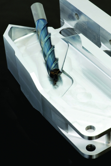
A three-flute tool finishes an aluminum part. Image courtesy of LMT Onsrud
“It comes down to tailoring a tool to a specific part and getting the most out of it that you can,” said Mitchell Parker, process improvement specialist for LMT Onsrud LP, Waukegan, Illinois. “You just have to have the right combination.”
“You think, ‘It is aluminum, and anything can cut it,’ so you can use any tool in the drawer,” he added. “To stay competitive, there are factors in making that high-performance tool that will get the material removal rates up.”
One cutter doesn’t fit all aluminum machining needs, so end users must work with toolmakers that have offerings across the spectrum.
“Because there are such a high variety of parts that are made of aluminum, you have to have a high variety of tools to serve the market,” said Alyssa Walther, automotive specialist for Irving, Texas-based OSG USA Inc., who’s based in Bensenville, Illinois.
Material Matters
A plethora of aluminum alloys are available, but the two most common are 6061-T6 and 7075, which MacArthur said is used usually to make aircraft components.
“The big player is the aerospace market,” he said.
Walther concurred that 6061 is a popular choice.
“It is one of the material grades that we keep around our R&D facility for testing,” she said.
In addition to the aerospace industry, Kyle Matsumoto, automotive specialist for OSG USA, noted that the industry he covers is a major consumer of aluminum, with a focus on high-volume production.
“The big difference between automotive and aerospace is the size of the parts,” he said, “such as machining huge wings.”
Those types of large aircraft parts previously were made of potentially dozens of components that were riveted, bolted or otherwise mechanically attached to each other but now are produced as monolithic structures, MacArthur said. To produce them, aircraft manufacturers sometimes turn 98% or 99% of a workpiece into chips while removing 32 kg (71 lbs.) or more of aluminum per minute.
As a result, cutting tool manufacturers have risen to the challenge.
“We are constantly coming out with a better version of what we did,” Walther said. “Tools that can reach a longer length and still keep chatter and vibration down are constantly evolving as the years go by.”
In addition to the various alloy compositions, aluminum comes as cast or wrought workpieces. Parker said cast can be more abrasive depending on the percentage of silicon. Therefore, cast aluminum often is machined at a slower cutting speed than wrought. LMT Onsrud recommends starting at about 244 to 305 m/min. (800 to 1,000 sfm) when cutting cast 6061 aluminum and 457 to 610 m/min. (1,500 to 2,000 sfm) when machining the wrought variety.
To avoid chip welding when milling aluminum, OSG USA offers tools with a diamondlike carbon coating. Image courtesy of OSG USA
“Those numbers are fine and good starting points,” he said. “But at the end of the day, when you are trying to lead the market or beat the competition, you’re not going to be at a low surface footage or low chip loads unless the material or the part dictates it. It depends on how clean the material is in the casting.”
MacArthur agreed that 305 m/min. is a nice starting point when machining cast aluminum with high silicon content but said a starting suggestion is unnecessary when cutting wrought aluminum.
“On the wrought side, we are unlimited,” he said. “We have customers taking a 1"-dia. (25 mm) tool at 33,000 rpm, which is a huge amount of surface footage.”
A tool well suited to cut aluminum starts with its substrate. An end user can apply an HSS tool, but carbide cutters generally are needed to boost removal rates and extend tool life. Parker recommends a carbide grade with less than 10% cobalt because it tends to stick to a tool when exposed to a high level of heat, resulting in built-up edge and dulling upsharp cutting edges. But a tool with too little cobalt might be too hard and therefore too brittle.
While a low-cobalt-content tool is fairly hard, to handle the high amount of horsepower needed to effectively cut aluminum, the tool also must be somewhat tough. That’s where grain size plays a role. MacArthur said the majority of tools with less than 10% cobalt have a submicron grain size.
“Because aluminum is easy to machine, you’re taking 149-kW (200-hp) cuts and removing 70-plus lbs. (32-plus kg) of material per minute, which generates a tremendous amount of force,” he said. “So you want the toughest tool that’s going to last the longest and give you the most wear resistance.”
Playing Flutes
When milling aluminum, the number of flutes on a tool is critical. Walther said a three-flute tool is common and effective for performing conventional roughing and semifinishing. Two-flute tools, however, provide an added benefit when slotting, deep pocketing and even finishing because their design enhances chip evacuation by providing the most amount of flute space.
“If you have a longer overhang and want a really smooth finish, typically the lower number of flutes will help reduce the amount of cutting vibration because there are only two points,” she said. “You’re basically indexing the tool 180° apart, so it gives the tool a chance to calm the chatter down.”
Although a two-flute tool is more ordinary for milling aluminum, Parker said LMT Onsrud offers three-flute roughers that help lower the considerable spindle load on a machine.
However, two- or three-flute tools are not the only options when cutting aluminum. Walther said end users performing high-efficiency machining, which generally involves running at high feed rates and taking deeper DOCs (step-downs) and a shallow WOC, are gravitating toward tools with four to seven flutes — or more.
“It depends on what the customer’s style of machining is,” she said.
RobbJack also sees that trend.
“We have special five-flute tools that are going to be standard now that people can use to machine at thousands of inches per minute and max out their machines doing high-efficiency machining,” MacArthur said.
Nonetheless, pushing a machine to its limits doesn’t mean stressing it and shortening its life.
“We are just making sure we are utilizing all the rpm and all the horsepower that the machine has,” MacArthur said. “We have tools that reduce the amount of horsepower that’s consumed so you can remove more cubic inches per minute with the same amount of horsepower.”
Slick Surfaces
Regardless of flute count, flutes should be highly polished to help clear chips and avoid re-cutting them.
“You want the substrate to be as slick as you can get it so nothing adheres to the cutting edge,” Parker said, adding that LMT Onsrud polishes flutes before and after depositing a coating.
He noted that the more flutes a tool has, the higher the helix angle is, which reduces the pull on a part. In addition, the more flutes a tool has, the larger the core is.
“The heavier the core your tool has is crucial,” Parker said. “You definitely need that because you’re applying a lot of forces on that tool by machining aluminum.”
When LMT Onsrud changes tool geometry to suit a specific application, the company bases the change on the horsepower and torque curve of a customer’s machine, he explained. He said the toolmaker can provide specials in about six days for uncoated tools and eight days for coated ones.
MacArthur said the most common helix angle for a rougher is from 35° to 40°. That design also can be suitable for finishing, which traditionally requires a slightly higher helix angle. RobbJack, for example, offers a combination tool for hogging and finishing.
“In the old days, you would rough with a two-flute tool and finish with a three,” he said. “We have the ability now with new geometry to hog with three flutes and finish with that same tool.”
A tool doesn’t necessitate the same geometry for each flute, and a variable helix and/or variable indexing is a well-established design to help minimize vibration.
“A significant portion of the newer tools that we’re developing and bringing in have a variable-geometry component to them,” Walther said.
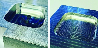
A comparison is shown of the surface finish imparted when applying (left) and not applying (right) a Mirror Edge tool. Image courtesy of RobbJack
MacArthur said RobbJack introduced a geometry that eliminates vibration and chatter by matching tooth passing frequency to part frequency. Called Mirror Edge, it achieves stable cutting conditions by combining polished flutes, various corner radii, through-coolant capability and chipbreakers. The geometry also eradicates witness marks and staircase-shaped grooves when, for example, deep pocketing and finishing deep walls, according to the company.
However, RobbJack reports that spring passes, which are cuts taken on a wall a second time or more that follow the same toolpath, might be needed to improve finish and deflection. Company test results show that up to four spring passes can be taken with specific tools without any negative effects.
“Normally, we do not recommend doing that, and we have tools and geometry to eliminate that,” MacArthur said. “It normally reduces tool life and lengthens cycle time. However, when the tool is sticking out and contacting the entire wall at a 5-1 length-to-diameter ratio, the tool has more flex. So a spring pass is necessary to get rid of flexing and taper in the wall.”
A Lubricious Layer
To help prevent BUE and extend tool life, Matsumoto said OSG USA can deposit a diamondlike carbon coating on tools for aluminum applications.
“We are trying to reduce the friction so we can avoid chip welding on the tools,” he said.
The coefficient of friction for OSG USA’s DLC coating is approximately 0.1.
Tools that cut aluminum commonly are uncoated. In those cases, Matsumoto recommends much polishing of tool surfaces to combat BUE.
MacArthur estimates that about 30% of RobbJack’s customers order tools with a DLC coating for machining aluminum while the rest choose uncoated tools.
“If you have gummy aluminums, coatings tend to be used more because they add lubricity,” he said. “Most of our customers are using the DLC coating for roughing operations, where they want to get more minutes or hours out of the tool.”
MacArthur said one disadvantage of a coating, even one only 2 µm to 3 µm (0.00008" to 0.00012") thick, is that it adds a small hone to a theoretical upsharp edge.
“If your parts are ultrasensitive to having the most razor-sharp edge,” he said, “then the uncoated is a hair sharper.”
Applying coolant also helps reduce friction, resist heat and minimize microfracturing of a tool, Parker said. However, external coolant may not penetrate all necessary part features, such as in a deep pocket if a tool is against a wall. When possible, he recommends through-coolant tools to avoid re-cutting chips and putting unnecessary heat into a part.
To further lessen heat going into a part and tool and instead send heat into chips, end users should examine their machining strategies. He said one that aids with maintaining a constant chip load is trochoidal milling, which is circular milling that includes simultaneous forward movements.
“I know a lot of people are not using radial chip thinning, so they are underutilizing the tool,” Parker said. “More times than not, they are rubbing and not producing the chip thickness that’s desired for a specific radial depth of cut.”
When all elements correctly come together, end users cutting aluminum would be wise to have adequate hearing protection.
“We even have a customer that is cutting so much aluminum that they have cut holes in a wall of the machine,” MacArthur said, adding that the wall was replaced but not the machine. “It sounds like a machine gun going off when they’re cutting aluminum.”
For more information about machining aluminum, view video presentations by RobbJack and LMT Onsrud at www.ctemag.com by entering this URL on your web browser: cteplus.delivr.com/2fbm4
Contact Details
Contact Details

Contact Details

Related Glossary Terms
- abrasive
abrasive
Substance used for grinding, honing, lapping, superfinishing and polishing. Examples include garnet, emery, corundum, silicon carbide, cubic boron nitride and diamond in various grit sizes.
- alloys
alloys
Substances having metallic properties and being composed of two or more chemical elements of which at least one is a metal.
- aluminum alloys
aluminum alloys
Aluminum containing specified quantities of alloying elements added to obtain the necessary mechanical and physical properties. Aluminum alloys are divided into two categories: wrought compositions and casting compositions. Some compositions may contain up to 10 alloying elements, but only one or two are the main alloying elements, such as copper, manganese, silicon, magnesium, zinc or tin.
- built-up edge ( BUE)
built-up edge ( BUE)
1. Permanently damaging a metal by heating to cause either incipient melting or intergranular oxidation. 2. In grinding, getting the workpiece hot enough to cause discoloration or to change the microstructure by tempering or hardening.
- built-up edge ( BUE)2
built-up edge ( BUE)
1. Permanently damaging a metal by heating to cause either incipient melting or intergranular oxidation. 2. In grinding, getting the workpiece hot enough to cause discoloration or to change the microstructure by tempering or hardening.
- chatter
chatter
Condition of vibration involving the machine, workpiece and cutting tool. Once this condition arises, it is often self-sustaining until the problem is corrected. Chatter can be identified when lines or grooves appear at regular intervals in the workpiece. These lines or grooves are caused by the teeth of the cutter as they vibrate in and out of the workpiece and their spacing depends on the frequency of vibration.
- coolant
coolant
Fluid that reduces temperature buildup at the tool/workpiece interface during machining. Normally takes the form of a liquid such as soluble or chemical mixtures (semisynthetic, synthetic) but can be pressurized air or other gas. Because of water’s ability to absorb great quantities of heat, it is widely used as a coolant and vehicle for various cutting compounds, with the water-to-compound ratio varying with the machining task. See cutting fluid; semisynthetic cutting fluid; soluble-oil cutting fluid; synthetic cutting fluid.
- cutting speed
cutting speed
Tangential velocity on the surface of the tool or workpiece at the cutting interface. The formula for cutting speed (sfm) is tool diameter 5 0.26 5 spindle speed (rpm). The formula for feed per tooth (fpt) is table feed (ipm)/number of flutes/spindle speed (rpm). The formula for spindle speed (rpm) is cutting speed (sfm) 5 3.82/tool diameter. The formula for table feed (ipm) is feed per tooth (ftp) 5 number of tool flutes 5 spindle speed (rpm).
- depth of cut
depth of cut
Distance between the bottom of the cut and the uncut surface of the workpiece, measured in a direction at right angles to the machined surface of the workpiece.
- endmill
endmill
Milling cutter held by its shank that cuts on its periphery and, if so configured, on its free end. Takes a variety of shapes (single- and double-end, roughing, ballnose and cup-end) and sizes (stub, medium, long and extra-long). Also comes with differing numbers of flutes.
- feed
feed
Rate of change of position of the tool as a whole, relative to the workpiece while cutting.
- flutes
flutes
Grooves and spaces in the body of a tool that permit chip removal from, and cutting-fluid application to, the point of cut.
- gang cutting ( milling)
gang cutting ( milling)
Machining with several cutters mounted on a single arbor, generally for simultaneous cutting.
- helix angle
helix angle
Angle that the tool’s leading edge makes with the plane of its centerline.
- high-speed steels ( HSS)
high-speed steels ( HSS)
Available in two major types: tungsten high-speed steels (designated by letter T having tungsten as the principal alloying element) and molybdenum high-speed steels (designated by letter M having molybdenum as the principal alloying element). The type T high-speed steels containing cobalt have higher wear resistance and greater red (hot) hardness, withstanding cutting temperature up to 1,100º F (590º C). The type T steels are used to fabricate metalcutting tools (milling cutters, drills, reamers and taps), woodworking tools, various types of punches and dies, ball and roller bearings. The type M steels are used for cutting tools and various types of dies.
- inches per minute ( ipm)
inches per minute ( ipm)
Value that refers to how far the workpiece or cutter advances linearly in 1 minute, defined as: ipm = ipt 5 number of effective teeth 5 rpm. Also known as the table feed or machine feed.
- lubricity
lubricity
Measure of the relative efficiency with which a cutting fluid or lubricant reduces friction between surfaces.
- milling
milling
Machining operation in which metal or other material is removed by applying power to a rotating cutter. In vertical milling, the cutting tool is mounted vertically on the spindle. In horizontal milling, the cutting tool is mounted horizontally, either directly on the spindle or on an arbor. Horizontal milling is further broken down into conventional milling, where the cutter rotates opposite the direction of feed, or “up” into the workpiece; and climb milling, where the cutter rotates in the direction of feed, or “down” into the workpiece. Milling operations include plane or surface milling, endmilling, facemilling, angle milling, form milling and profiling.
- polishing
polishing
Abrasive process that improves surface finish and blends contours. Abrasive particles attached to a flexible backing abrade the workpiece.
- slotting
slotting
Machining, normally milling, that creates slots, grooves and similar recesses in workpieces, including T-slots and dovetails.
- toolpath( cutter path)
toolpath( cutter path)
2-D or 3-D path generated by program code or a CAM system and followed by tool when machining a part.
- wear resistance
wear resistance
Ability of the tool to withstand stresses that cause it to wear during cutting; an attribute linked to alloy composition, base material, thermal conditions, type of tooling and operation and other variables.
- web
web
On a rotating tool, the portion of the tool body that joins the lands. Web is thicker at the shank end, relative to the point end, providing maximum torsional strength.
Author

Alan Richter, a 40-year veteran journalist, has spent the last 25 years covering the metalworking industry for Cutting Tool Engineering and currently serves as its editor-at-large. Contact him at [email protected].
Contributors
LMT Onsrud LP
800-234-1560
www.onsrud.com
OSG USA Inc.
800-837-2223
www.osgtool.com
RobbJack Corp.
844-342-0222
www.robbjack.com
