VISI 2021 CAD, Mold, Progress, CAM, Simulation and Wire Functions
VISI 2021 CAD, Mold, Progress, CAM, Simulation and Wire Functions
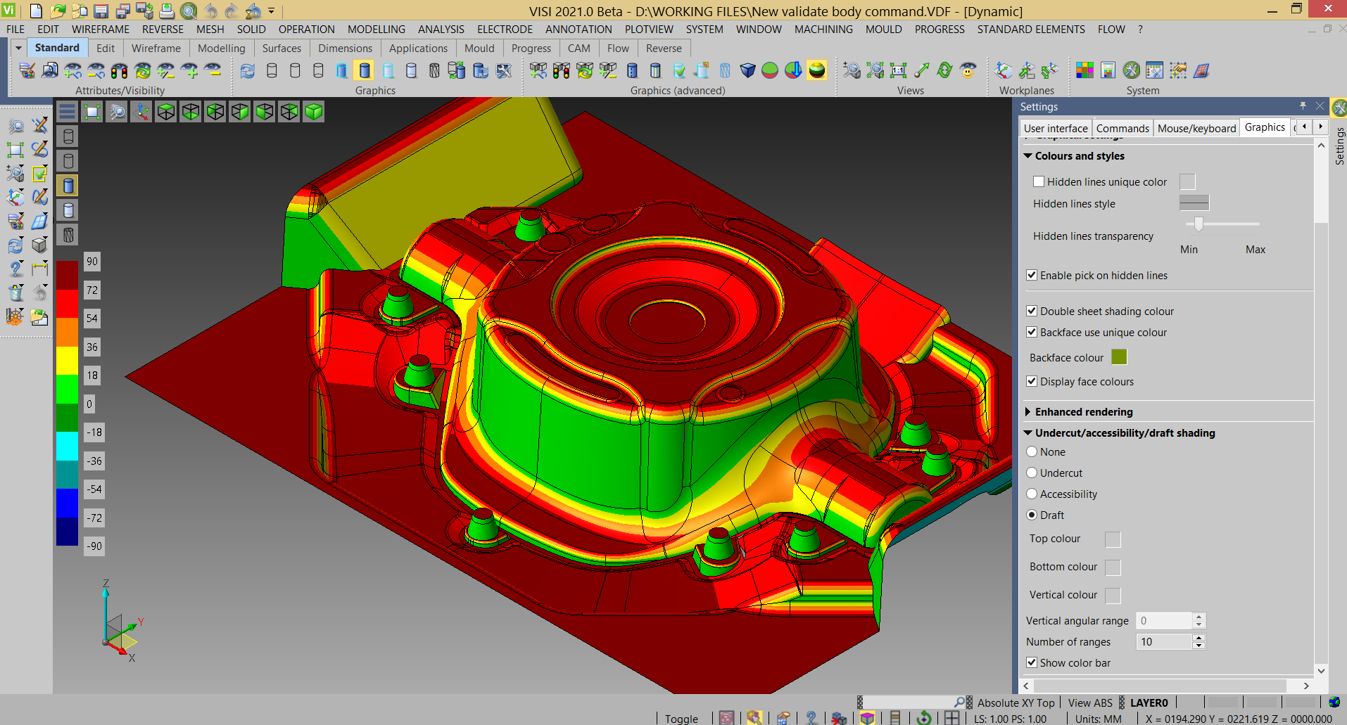
CAD analysis benefits from a new function which improves the suite of analysis-shading modes. Draft Analysis has been added to the existing Undercut and Accessibility shading, performing an on-the-fly analysis of the draft angle. This uses the same technique as in the undercut mode, but extended to more ranges. The colors and angular value of each range can be changed by simply clicking on the colors or numeric labels on the graphics toolbar.

A raft of new and enhanced functionality features in VISI 2021 – the latest release of Hexagon's specialist mold and die CAD/CAM software.
CAD
CAD analysis benefits from a new function which improves the suite of analysis-shading modes. Draft Analysis has been added to the existing Undercut and Accessibility shading, performing an on-the-fly analysis of the draft angle. This uses the same technique as in the undercut mode, but extended to more ranges. The colors and angular value of each range can be changed by simply clicking on the colors or numeric labels on the graphics toolbar.
Repair functions used in the Repair Invalid Faces of Bodies command are now integrated in the Validate command. It is now also possible to zoom in on any potential issues using the Auto Zoom function.
Developments to the CAD Reverse module enhanced the Reverse and Casting processes. VISI Product Manager Marco Cafasso xplains that the scanning operation has been improved with the shaded view, giving better and faster feedback. "Also, new features have been added to increase the probing solution. 'Leapfrog' management in Casting has been reviewed to guarantee correct scanning with the laser tracker, for both small and large parts. And Reverse projects now benefit from faster and more precise surface creation."
With Point Scanning, the shaded point cloud is now shown during the scanning operation, giving the operator an immediate view of what has been correctly scanned, and if anything is missing.
An additional option has been added to automatically create a mesh as a scanning result, which Cafasso says is particularly valuable when a quicker, rather than detailed, result is needed.
Enhancements to probing during the Reverse process now detect the correct diameter of the part in relation to the position of the probed points. A Circle/Slot probing feature has been added for probing and designing a circle or slot, giving several options to guarantee the probed element is the correct size and in the correct position.
"The new Curve probing feature allows the user to probe a curve alongside the part. This can save time where curves are used to identify the shape – they can be used to create the relative surfaces, avoiding the need to create a mesh first."
All features relative to surface creation when working on planes, radii, and cones from the mesh have been reviewed, leading to time savings and better quality surfaces during model preparation. "There's now the ability to define the reference direction or surface of some constraints. While creating the surface, users can select a direction, and then add the constraint type – parallel, perpendicular or concentric."
A Mesh to Advanced Surface feature has been added for creating a good quality surface, representing an alternative to the standard Mesh to Surface command.
MOLD – Body to Mold
Additional options to existing commands, along with new items of functionality, make part position management considerably easier.
With Body to Mold, there is a new option for selecting multiple elements, including solids and surfaces, and moving the selected bodies to the mold position. During part positioning, 'not uniform scaling values' can now be defined by the user and the system automatically sets the relative shrinkage data in a special Assembly Manager field.
With Mold to Body, the system allows multiple elements to be selected, including solids and surfaces, and to move he complete mold back into Body position. "This will be valuable for operators using CMMs to check tools in the body position. When they select the part to move back, they get an option to select multiple elements to go with the tool back to Body position, Caffasso says.
When browsing mold parts, the system lists those which have been defined as 'body to mold,' showing all relevant data. And defined 'shrinkage' data can be edited in the 'reset scale on parts' function.
PROGRESS - Part Unfolding
To provide a powerful and complete solution to this new unfolding approach, additional features have been included for flanges and parts with non-linear blends. "The aim is to study and modify a part, preserving the links between the different unfolding steps."
The Part Definition feature has been improved, delivering better and faster part analysis, identifying the different face types, defining material, and setting linear bends for unfolding. Different colors can be set in relation to different neutral-fiber values, providing quick identification for unfolded linear bends and fiber values. "After automatically analyzing the part, VISI 2021 can now edit the face recognition, giving a warning description, meaning the user can better understand why an operation has failed, making it easier to decide on a different approach."
A new feature manages flange unfolding on the analyzed part, and shows the result in preview mode so the operator can evaluate the result and set different parameters while preserving the link with the original part. This automatically recalculates the flanged part, meaning that all linked parts can then be rebuilt in reference to a modification on the original.
CAM Simulation
An interface with Hexagon's G-code simulator, NCSIMUL Advanced, is offered as a cost option in VISI 2021. Cafassoexplains that NCSIMUL manages the complete machining process from the NC program to the machined part. "Its capabilities include automatic G-code reprogramming, G-code simulation and cutting-tool management."
Significant benefits include:
· Read and simulate any G-code and machine tool macros
· Preview toolpath G-code program analysis to detect errors before simulation
· Precise material removal and machine simulation
· Integrated G-code program editor for online modification
· Dimensional analysis
· Analysis and optimization of cutting conditions.
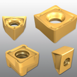
An enhanced waveform algorithm prevents tool damage around pegs (or thin walls) left during the milling process. Those areas are now identified, and the XY step reduced, smoothing the corners. This reduces tool stress, making damage or breakage much less likely.
WIRE
Finally, VISI 2021 introduces a new command, which duplicates an existing wire EDM machine, improving project management for manufacturers using two or more different models from the same machine manufacturer, such as Sodick and Agie.


