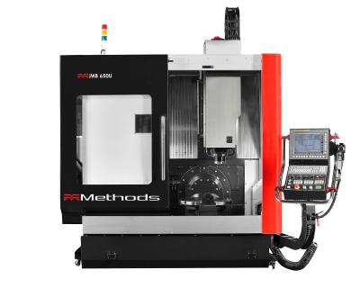
Methods Machine Tools Inc. has introduced a new line of Methods-branded 3-axis vertical and 5-axis bridge-type machining centers, all engineered and built to Methods' highest specifications and quality standards. The Methods Machining Centers are available in North America, and offer an affordable, accurate and reliable best-in-class mid-range machining solution.
"We are very pleased to announce the introduction of Methods Machining Centers," said Mark Wright, president and CEO of Methods Machine Tools Inc. "Methods' engineering team has ensured that our new branded line meets our customers' needs and expectations in North America. These machines will provide an ideal value-to-performance solution in the marketplace and complement our full portfolio of leading lines."
Methods Machining Centers are made to Methods' design and engineering standards by Litz Hitech Corp., a reputable, well-established machine tool builder, and are fully backed by Methods service and support. All Methods machining centers are fully inspected to meet strict quality and design specifications, and also be in compliance with ISO/ASME standards. Laser and ball bar testing ensures performance and accuracy of each machine.
Methods 3-axis VMCs include four initial models: MV 800H, MV 1000H, MV 1100H and MV 1600H. The feature a 15,000-rpm, 30-hp BIG-PLUS 40-taper direct-drive spindle with oil-air lubrication and spindle oil chiller, providing power, speed, enhanced surface finishing, long spindle life and thermal stability. Rigid box-way construction in the Z-axis utilizing Turcite B ensures exceptional cutting performance and machining accuracy. Turcite B technology was specifically developed to provide machines with superior rigidity, low friction coefficient, reduced vibration, excellent damping characteristics without stick-slip and high wear resistance for long machine life.
Additional features in the Methods VMCs include thermal compensation using three thermocouples to allow the software to compensate for actual thermal growth. The MV 800H and MV 1000H have robust 1.378 inch (35mm) roller guideways in the X and Y-axis with 2,362-ipm rapids. The MV 1100H has a larger structure with 1.77 inch (45 mm) roller guideways in the X and Y-axis with a 1,890-ipm rapid rate, and its Z-axis box ways are over 3 inches wider (side-to-side) than the MV 800H and MV 1000H. The MV 1600H is a heavy-duty 41,888-lb. machine designed for exceptional cutting performance on large, diverse, complex parts. The MV 1600H has an impressive 21.85 inch distance between Z-axis box ways (side to side) and offers 2.17 inch (55 mm) roller guideways in the X and Y-axis with 1,417 IPM rapid rates. Automatic tool changers range from 24 tools to 40 tools, depending on the machine.
Methods MB 650U 5-axis bridge-type machining center is designed for the high accuracy, 5-axis simultaneous machining of complex parts and significantly reduces the need for multiple setups. Equipped with standard linear scales on the X, Y and Z axes, rotary scales on the B and C axes, and thermal compensation results in stable, high precision part production. The MB 650U has a 15,000-rpm, 25-hp BIG-PLUS 40-taper direct-drive spindle with oil-air lubrication and spindle oil chiller for long spindle life. This performance package also includes a calibration ball, TCP software and probe system for setting/calibrating precise tool center point. A laser tool measurement system detects tool wear, damage and breakage, reducing non-productive time and enabling automated operation.
All Methods Machining Centers feature FANUC controls, the industry's benchmark for quality and reliability. Methods VMCs have the FANUC 0iMF control with 10.4 inch LCD screen, manual guide I, AICC II, 2-m/sec block processing time (BPT) and 200-block look-ahead. For the high level of performance and processing power required for complex 5-axis machining, the MB 650U bridge-type machining center features the FANUC 31iMB5 control with 15 inch TFT screen including a data server, manual guide I, AICC II, 1 MB of NC memory, .4ms BPT, 600-block look-ahead, collision detection (built in 3D interference check), Fast Package III, Ethernet and 2GB CF card.
"We are confident that our new Methods Machining Centers will exceed customer expectations for quality, reliability, accuracy and longevity at a competitive price," said Jeff Ervay, Methods brand product manager. “To meet the needs of our customers, we are continuing the development of the Methods product line with additional models in the future.”
Contact Details
Related Glossary Terms
- calibration
calibration
Checking measuring instruments and devices against a master set to ensure that, over time, they have remained dimensionally stable and nominally accurate.
- centers
centers
Cone-shaped pins that support a workpiece by one or two ends during machining. The centers fit into holes drilled in the workpiece ends. Centers that turn with the workpiece are called “live” centers; those that do not are called “dead” centers.
- inches per minute ( ipm)
inches per minute ( ipm)
Value that refers to how far the workpiece or cutter advances linearly in 1 minute, defined as: ipm = ipt 5 number of effective teeth 5 rpm. Also known as the table feed or machine feed.
- look-ahead
look-ahead
CNC feature that evaluates many data blocks ahead of the cutting tool’s location to adjust the machining parameters to prevent gouges. This occurs when the feed rate is too high to stop the cutting tool within the required distance, resulting in an overshoot of the tool’s projected path. Ideally, look-ahead should be dynamic, varying the distance and number of program blocks based on the part profile and the desired feed rate.
- machining center
machining center
CNC machine tool capable of drilling, reaming, tapping, milling and boring. Normally comes with an automatic toolchanger. See automatic toolchanger.
- numerical control ( NC)
numerical control ( NC)
Any controlled equipment that allows an operator to program its movement by entering a series of coded numbers and symbols. See CNC, computer numerical control; DNC, direct numerical control.
- wear resistance
wear resistance
Ability of the tool to withstand stresses that cause it to wear during cutting; an attribute linked to alloy composition, base material, thermal conditions, type of tooling and operation and other variables.

