Submarine propellers traditionally take a long time to produce. They are large and have tight tolerances, and so when the Naval Foundry and Propeller Center (NFPC) in Philadelphia was looking to upgrade its large-machining capability with high-speed machines it considered equipment from across the world.
About eight years ago, NFPC started a research program to test high-speed machining of propellers made from Copper-based alloys. Successful testing led to a search for high-speed machines that could accommodate the largest submarine propellers of up to 24’ (731.2 cm) in diameter.
The search ended with the selection of the Starrag Group’s Droop+Rein FOGS machine, said Faris Ibrahim, project manager and mechanical engineer at the NFPC. “From that day in 2005, we started an excellent relationship with Starrag which led to another Droop+Rein FOGS purchased in 2012, and three more in 2019, and we will need many more in the future.”
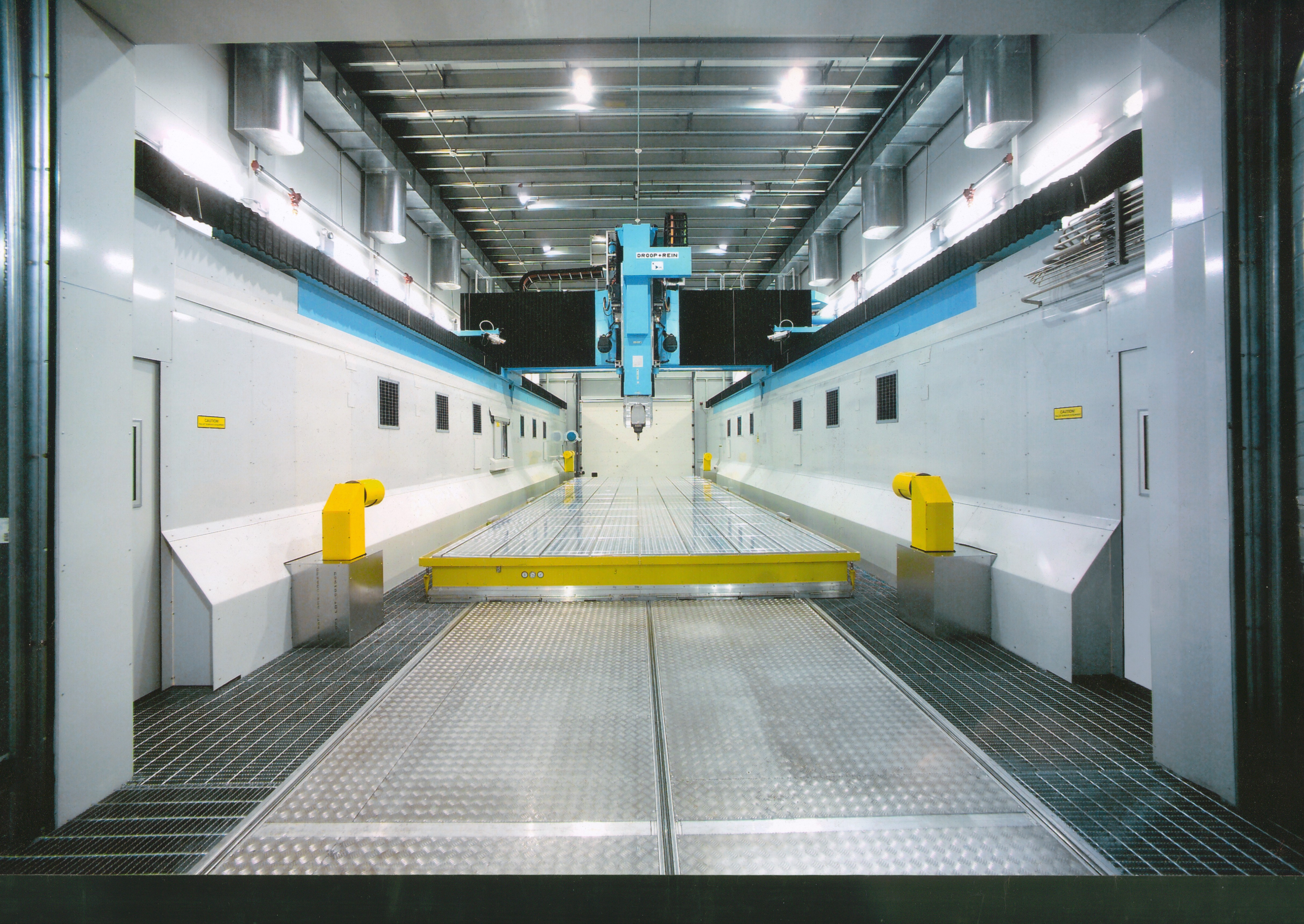
Starrag successfully delivered in 2007 and 2012 two Droop+Rein high-speed machining centers. The Droop+Rein FOGS 70 68 TT M30 C machine had to meet the Navy's specifications. The machine met the following dimensions: X-axis: 267” (6,781.8 mm), Y-axis: 275” (6,985 mm), Z-axis: 90” (2,286 mm), rotary table 275” with a main power drive of 2x134 hp). The twins are the biggest machine tools in the history of FOGS-machines. They are turning, drilling and contour milling the US Navy’s submarine propellers.
The next three Droop+Rein machines were successfully delivered in 2019. These machines were the FOGS 70 68 M 30 K, FOGS 75 75 TT M30 C, and FOGS 85 85 TT M30 C.
The NFPC is the US Navys only submarine propeller producing facility, and the Droop+Rein high speed machines are doing all of the finish machining work. “They’ve become the workhorses of our shop,” said Ibrahim. “Our investment is paying off with improved surface finish and accuracy.”
The machining requirements are very high, he said, especially considering the propellers are made of a Copper alloy that is difficult to machine. Additionally, the blades have a complex geometry with local accuracies on the order of 0.010” or 254 µm. The propeller has complex curvatures modelled in a CAM system to produce complex cutting motion that the Droop+Rein FOGS machine must reproduce extremely accurately with its six axes. Ibrahim said that “the capability of the machine control combined with high speed cutting, allows us to produce almost mirror finish sculpted surfaces.”
The excellent results are also based on special machine tool characteristics, said Ibrahim. “When we had our first meeting after the contract was awarded, we presented the Starrag team a difficult task. We needed a special head to machine between the tightly stacked blades. After many discussions and simulation studies, the Starrag team presented us with a unique head design that eventually became the 'Hammer Head.'. This head gave us the ability to easily reach and contour every part of the propeller. It was a brilliant design that really showcased their technical ability.”
Starrag Group is a global technology leader in manufacturing high-precision machine tools for milling, turning, boring and grinding workpieces of metallic, composite and ceramic materials. Its North American headquarters can be reached at 859-534-5201 or visit them at www.starrag.com.
Contact Details
Related Glossary Terms
- alloys
alloys
Substances having metallic properties and being composed of two or more chemical elements of which at least one is a metal.
- boring
boring
Enlarging a hole that already has been drilled or cored. Generally, it is an operation of truing the previously drilled hole with a single-point, lathe-type tool. Boring is essentially internal turning, in that usually a single-point cutting tool forms the internal shape. Some tools are available with two cutting edges to balance cutting forces.
- centers
centers
Cone-shaped pins that support a workpiece by one or two ends during machining. The centers fit into holes drilled in the workpiece ends. Centers that turn with the workpiece are called “live” centers; those that do not are called “dead” centers.
- computer-aided manufacturing ( CAM)
computer-aided manufacturing ( CAM)
Use of computers to control machining and manufacturing processes.
- gang cutting ( milling)
gang cutting ( milling)
Machining with several cutters mounted on a single arbor, generally for simultaneous cutting.
- grinding
grinding
Machining operation in which material is removed from the workpiece by a powered abrasive wheel, stone, belt, paste, sheet, compound, slurry, etc. Takes various forms: surface grinding (creates flat and/or squared surfaces); cylindrical grinding (for external cylindrical and tapered shapes, fillets, undercuts, etc.); centerless grinding; chamfering; thread and form grinding; tool and cutter grinding; offhand grinding; lapping and polishing (grinding with extremely fine grits to create ultrasmooth surfaces); honing; and disc grinding.
- milling
milling
Machining operation in which metal or other material is removed by applying power to a rotating cutter. In vertical milling, the cutting tool is mounted vertically on the spindle. In horizontal milling, the cutting tool is mounted horizontally, either directly on the spindle or on an arbor. Horizontal milling is further broken down into conventional milling, where the cutter rotates opposite the direction of feed, or “up” into the workpiece; and climb milling, where the cutter rotates in the direction of feed, or “down” into the workpiece. Milling operations include plane or surface milling, endmilling, facemilling, angle milling, form milling and profiling.
- turning
turning
Workpiece is held in a chuck, mounted on a face plate or secured between centers and rotated while a cutting tool, normally a single-point tool, is fed into it along its periphery or across its end or face. Takes the form of straight turning (cutting along the periphery of the workpiece); taper turning (creating a taper); step turning (turning different-size diameters on the same work); chamfering (beveling an edge or shoulder); facing (cutting on an end); turning threads (usually external but can be internal); roughing (high-volume metal removal); and finishing (final light cuts). Performed on lathes, turning centers, chucking machines, automatic screw machines and similar machines.
Author
News items authored by Cutting Tool Engineering have been written or edited by the editors of Cutting Tool Engineering magazine. The reports represent material submitted to CTE by outside authors, and edited by CTE editors for style and accuracy.