 By Scott Laprade, applications supervisor for Genevieve Swiss Industries Inc.
Investing in CNC Swiss technology allows a shop to perform threading operations. Every Swiss machinist should be aware of the latest advancements in this field.
When threading using a traditional ‘single-point’ method on a Swiss machine, or any lathe for that matter, it requires several passes with the tool to achieve full depth of the thread form. This tends to not be too much of a concern on larger diameter screws that use 60 degree included thread forms as the metal removal rate is low and workpiece deflection is minimal. Therefore, the tool pressure required to cut these kinds of threads is relatively low as well.
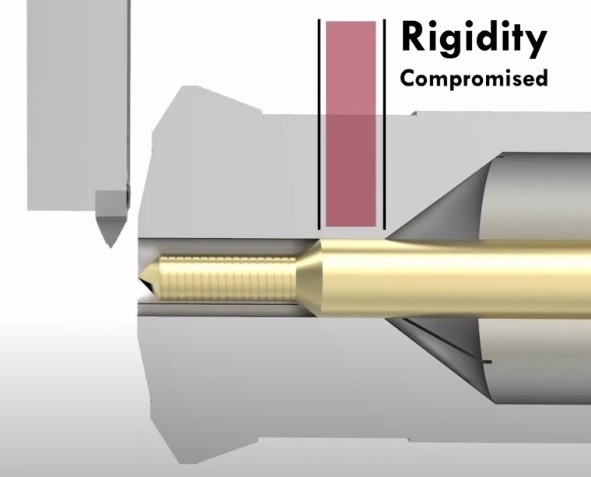
However, due to the sliding headstock and guidebushing arrangement of this equipment and the features or requirements of the workpiece being machined, this can lend opportunity for the workpiece to ‘fall out’ of the guidebushing as it is passed back and forth through the threading tool resulting in deflection and loss of rigidity. These phenomena become more prevalent when the thread major diameter is smaller than stock diameter. Support provided by the guidebushing is ineffective. Then consider some of the metal removal required to make more aggressive ‘buttress’ style threads such as those commonly found on orthopedic and trauma repair surgical implant designed to affix bone, single point threading becomes a lesser means to get the job done in a cost effective manner. Some of these deep threads can require as much as 40 to 50 passes to complete, depending on thread features.
The basics of one-pass threads
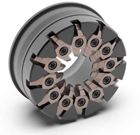 Here’s where thread whirling can be applied to increase the production capabilities of this kind of thread. To perform thread whirling work requires four components: a CNC Swiss/Sliding headstock lathe, a dedicated live tool ‘whirling attachment’ engineered specifically for this process, a cutter ring and body, and the actual carbide cutting tools with the requisite form precision ground into them. These tooling components work in concert to ‘whirl’ bar stock from stock diameter to a finished standard or custom thread form in a single pass.
The cutting action is a milling process similar to inner-diameter thread milling but on the outer-diameter of the workpiece. This gives unprecedented control over finish quality and speed by ensuring the material stays rigid within the guidebushing but also through modulating the chip load per tooth and C-axis RPM. Higher metal removal rates and increased finishes can be achieved through employing as many cutters in the cutter body as possible. When paired with high pressure coolant capability commonly found on most current machines, the cutting zone can be kept clear and free of swarf. As a result, high speeds are attainable resulting in burr-free finished threads in a single pass.
There have bee a number of advancements to this process including the development of carbide coatings. For example, UTILIS AG of Switzerland has introduced its proprietary “UHM10 TX+” tooling that is a carbide substrate and coating combination proving to be a knockout punch for not only titanium and medical stainless applications but also high temp alloys. This new coating technology features a defect-free, sub-micro surface quality that lends itself to the kinds of cutting load encountered by the carbide when thread whirling.
Edge quality is a major player in maintaining thread form accuracy and the TX+ offering strengthens the edge condition without deforming the shape of the geometry. This is an important aspect to the process because the lead angle adjustment, tool center position and insert accuracy is critical to produce perfect threads on the workpiece, especially on thread major diameters below 3mm where the thread crest sharpness may be a major requirement.
 When producing small diameter specialty thread forms, rigidity of the setup and distance from the guidebushing can become a concern. This has been traditionally addressed by obtaining an ‘extended nose’ guidebushing to hold the stock and workpiece closer to the thread whirling insert ‘flight circle’ to prevent finish and insert ruining harmonics from developing. Running an extended nose guidebushing can become cumbersome as traditional turning tools now need to be shifted outward from the tool plate to compensate for the guidebushing shift. It is a lot of extra work that is required to go into the setup to make the whirling operation work down at these smaller diameter workpieces.
An alternative is to bring the insert flight circle closer to the workpiece. For a wide selection of commercially available whirling attachments either from machine tool builder OEMs or on the aftermarket, there are now cutter rings with built-in positive shifts in the insert flight circle positioning. For example, lets state a lathe’s live whirling tool positioning has a 15mm distance from the standard guidebushing to the centerline of the carbide insert. The job requires whirling a 2.5mm major diameter, double lead buttress style thread form in 6AL-4V titanium. The shop has small diameter bar stock to produce these threads. While this is the perfect type of thread for whirling, the diameter requires us to lend special care in controlling the vibration that can occur from cutting 2 leads at the same time from the stock diameter. Here is where a shifted ring that advances the insert flight circle closer to the standard length guidebushing to make up some of that distance. A simple Y-shift correction is made to re-center the insert form on the cutting position of the bar stock. Often it is possible to achieve success using a shifted ring without an extended nose guidebushing.
Speed it up and cool it down
Modern Swiss lathes are coming out with live tooling drives capable of much faster speeds right out of the box, largely in part from advancements in smart motor technology but also pushed from a necessity of more rotational speed for use with micro tooling. Many models feature live tooling speeds from 5k to 10k RPM on the live tooling drive. A consideration that should be made when implementing whirling on a job is any micro end milling or live micro drilling work that may need to be accomplished in addition to the thread whirling. Whirling jobs tend to only require 2000 to 3000 rpms at the live tool for most applications whereas additional live tooling job requirements for micro tooling may require the motor to drive at full available speed, subjecting the whirling spindle to speeds it otherwise might not need to be operated at. Most Swiss machine models drive all live tooling on the tool positions in question from one singular motor. As such, when running a drill or end-mill, the whirling spindle will also be turning at this higher RPM while not in the cut subjecting it to added wear and tear. A good way to optimize the setup to get not only the best productivity out of the machine but also to get greater longevity out of a whirling spindle, and other live tools, is to pair the machine with a high-speed spindle unit that can help reduce the overall motor speed running the live tooling while maintaining the optimum surface speed for the micro tool operation. Gear driven speed multiplier spindles are readily available for many makes and models of Swiss machines.
Other considerations in the setup that should never be overlooked is the ability to provide adequate cooling and chip evacuation from the cutting zone. Previously, this was commonly achieved by running a high-pressure coolant line to the cutting zone and carefully aiming the jet stream using a bendable piece of tubing. This is effective at clearing the granular chip created by the whirling action but can be cumbersome to adjust and precisely aim, adding costly setup time to the job.
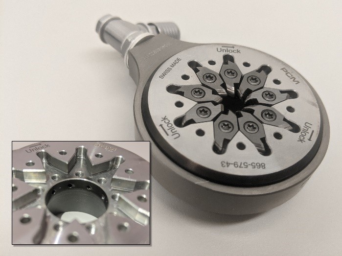
New products are available including a coolant-thru jet equipped with whirling attachments and cutter rings developed by PCM Willen SA of Switzerland for its line of whirling attachments. This streamlined setup can ensure reliable coolant delivery that pushes the cutting fluid to the cutting zone helping evacuate chips and maintaining lubricity and tool life extending cooling. Coolant and high-pressure oil are pushed through the cutter ring itself and into coolant channels internal to the cutter ring. The high-pressure oil jets are angled just slightly and calibrated to work with the insert’s gage length, eliminating any question of whether lubricity and optimal cooling is achieved. The added benefit of the new coolant ring design is they also can affix from the back side of the whirling attachment via small spring detent locking screws, which can save time when the time comes to index the carbide to a fresh edge. Paired with high-pressure quick release lines swapping over inserts is easier than ever.
Stay out in front
Make no mistake, aggressive screw threads are going to continue to be a staple in the medical orthopedic industry and there is no better way of producing them reliably with the speed, level of finish and quality control that the whirling process provides. Upgrading to whirling for more basic threads such as UNC/UNF threads on long parts, a cost savings can also be realized, especially when working with materials that produce stringy ductile chips or applications that require segmenting the thread to prevent dropping out of the guidebushing. By making sure your processes are using the leading-edge tooling technology available your operation will be able to stay competitive and ahead of the curve for years to come.
Contact Details
Related Glossary Terms
- alloys
alloys
Substances having metallic properties and being composed of two or more chemical elements of which at least one is a metal.
- computer numerical control ( CNC)
computer numerical control ( CNC)
Microprocessor-based controller dedicated to a machine tool that permits the creation or modification of parts. Programmed numerical control activates the machine’s servos and spindle drives and controls the various machining operations. See DNC, direct numerical control; NC, numerical control.
- coolant
coolant
Fluid that reduces temperature buildup at the tool/workpiece interface during machining. Normally takes the form of a liquid such as soluble or chemical mixtures (semisynthetic, synthetic) but can be pressurized air or other gas. Because of water’s ability to absorb great quantities of heat, it is widely used as a coolant and vehicle for various cutting compounds, with the water-to-compound ratio varying with the machining task. See cutting fluid; semisynthetic cutting fluid; soluble-oil cutting fluid; synthetic cutting fluid.
- cutting fluid
cutting fluid
Liquid used to improve workpiece machinability, enhance tool life, flush out chips and machining debris, and cool the workpiece and tool. Three basic types are: straight oils; soluble oils, which emulsify in water; and synthetic fluids, which are water-based chemical solutions having no oil. See coolant; semisynthetic cutting fluid; soluble-oil cutting fluid; synthetic cutting fluid.
- gang cutting ( milling)
gang cutting ( milling)
Machining with several cutters mounted on a single arbor, generally for simultaneous cutting.
- knockout
knockout
Mechanism for releasing workpieces from a die. It is also called ejector, kickout, liftout or shedder.
- lathe
lathe
Turning machine capable of sawing, milling, grinding, gear-cutting, drilling, reaming, boring, threading, facing, chamfering, grooving, knurling, spinning, parting, necking, taper-cutting, and cam- and eccentric-cutting, as well as step- and straight-turning. Comes in a variety of forms, ranging from manual to semiautomatic to fully automatic, with major types being engine lathes, turning and contouring lathes, turret lathes and numerical-control lathes. The engine lathe consists of a headstock and spindle, tailstock, bed, carriage (complete with apron) and cross slides. Features include gear- (speed) and feed-selector levers, toolpost, compound rest, lead screw and reversing lead screw, threading dial and rapid-traverse lever. Special lathe types include through-the-spindle, camshaft and crankshaft, brake drum and rotor, spinning and gun-barrel machines. Toolroom and bench lathes are used for precision work; the former for tool-and-die work and similar tasks, the latter for small workpieces (instruments, watches), normally without a power feed. Models are typically designated according to their “swing,” or the largest-diameter workpiece that can be rotated; bed length, or the distance between centers; and horsepower generated. See turning machine.
- lead angle
lead angle
Angle between the side-cutting edge and the projected side of the tool shank or holder, which leads the cutting tool into the workpiece.
- lubricity
lubricity
Measure of the relative efficiency with which a cutting fluid or lubricant reduces friction between surfaces.
- milling
milling
Machining operation in which metal or other material is removed by applying power to a rotating cutter. In vertical milling, the cutting tool is mounted vertically on the spindle. In horizontal milling, the cutting tool is mounted horizontally, either directly on the spindle or on an arbor. Horizontal milling is further broken down into conventional milling, where the cutter rotates opposite the direction of feed, or “up” into the workpiece; and climb milling, where the cutter rotates in the direction of feed, or “down” into the workpiece. Milling operations include plane or surface milling, endmilling, facemilling, angle milling, form milling and profiling.
- quality assurance ( quality control)
quality assurance ( quality control)
Terms denoting a formal program for monitoring product quality. The denotations are the same, but QC typically connotes a more traditional postmachining inspection system, while QA implies a more comprehensive approach, with emphasis on “total quality,” broad quality principles, statistical process control and other statistical methods.
- swarf
swarf
Metal fines and grinding wheel particles generated during grinding.
- threading
threading
Process of both external (e.g., thread milling) and internal (e.g., tapping, thread milling) cutting, turning and rolling of threads into particular material. Standardized specifications are available to determine the desired results of the threading process. Numerous thread-series designations are written for specific applications. Threading often is performed on a lathe. Specifications such as thread height are critical in determining the strength of the threads. The material used is taken into consideration in determining the expected results of any particular application for that threaded piece. In external threading, a calculated depth is required as well as a particular angle to the cut. To perform internal threading, the exact diameter to bore the hole is critical before threading. The threads are distinguished from one another by the amount of tolerance and/or allowance that is specified. See turning.
- turning
turning
Workpiece is held in a chuck, mounted on a face plate or secured between centers and rotated while a cutting tool, normally a single-point tool, is fed into it along its periphery or across its end or face. Takes the form of straight turning (cutting along the periphery of the workpiece); taper turning (creating a taper); step turning (turning different-size diameters on the same work); chamfering (beveling an edge or shoulder); facing (cutting on an end); turning threads (usually external but can be internal); roughing (high-volume metal removal); and finishing (final light cuts). Performed on lathes, turning centers, chucking machines, automatic screw machines and similar machines.