Composite material cutters offer a growing opportunity for toolmakers
The aerospace and defence, wind energy, automotive, civil construction and sporting goods industries have all come to adopt composites for high-performance applications – and the…
Article from ANCA
The idea of using fibers embedded in a supporting matrix has been around longer than initially appreciated. From the earliest beginnings of mud bricks reinforced with straw – to the first composite bows made with wood, bone and pine resin – it was recognized that composite materials deliver superior properties than if used in isolation.
The aerospace and defence, wind energy, automotive, civil construction and sporting goods industries have all come to adopt composites for high-performance applications – and the demand continues to grow. A report by Credence Research in 2019 estimated a CAGR of 9.3% for carbon fiber-reinforced plastics during the period 2017-2025. Duncan Thompson, product manager at ANCA, notes the increased sales inquiries in this area, reflecting a growing demand by tool manufacturers to produce cutting tools to service this specialist market.
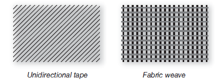
Composites can have unidirectional fiber layout, or bidirectional weave.
Duncan comments: “Commercial applications for composites continues grow, and with that, the market space for specialised cutting tools also expands. Cutting tool manufacturers need to adopt a variety of cutting tool designs and technologies, developing specialized tools for the wide and varied range of composites used today. ANCA has been working with customers to design innovative software that help address these needs, creating new tool geometries, and machines that can grind or erode market leading CFRP cutting tool solutions.
“Demand for specialised composite cutting tools will only continue to increase, presenting great market opportunities for tool makers with the right knowhow and manufacturing capabilities. With industry leading tool design software and tool manufacturing machines, ANCA continues to work closely with its customers at the cutting edge of the composite cutting tool market.”
Understanding the Composite Market
Today’s composites industry uses a variety of matrix materials, such as thermoset epoxy, phenolic and polyimide, and fibers, such as carbon, Kevlar and glass, to suit different applications. In a polymer matrix composite material, the matrix itself is not ductile like metal. Instead, it tends to be soft but very tough. Cutting metal involves plastic deformation forming chips that serve to remove heat from the point of cutting. Conversely, when analyzed at the micro level, machining of polymer matrix does not form chips, but rather a fine “dust” that results from localized fracturing. Heat is not readily transported away from the cutting edge by the matrix due to its low thermal conductivity. The next challenge comes from the embedded fibers, which are strong, stiff and highly abrasive when cut. Different composite manufacturing methods call for use of unidirectional tape or bidirectional fabric weave layered in different directions to suit the application. These will behave differently.
To complicate matters more, CFRP can be stacked with aluminium or titanium support in structural applications. These conditions create machining operations that need one tool to cut materials with dramatically different properties.
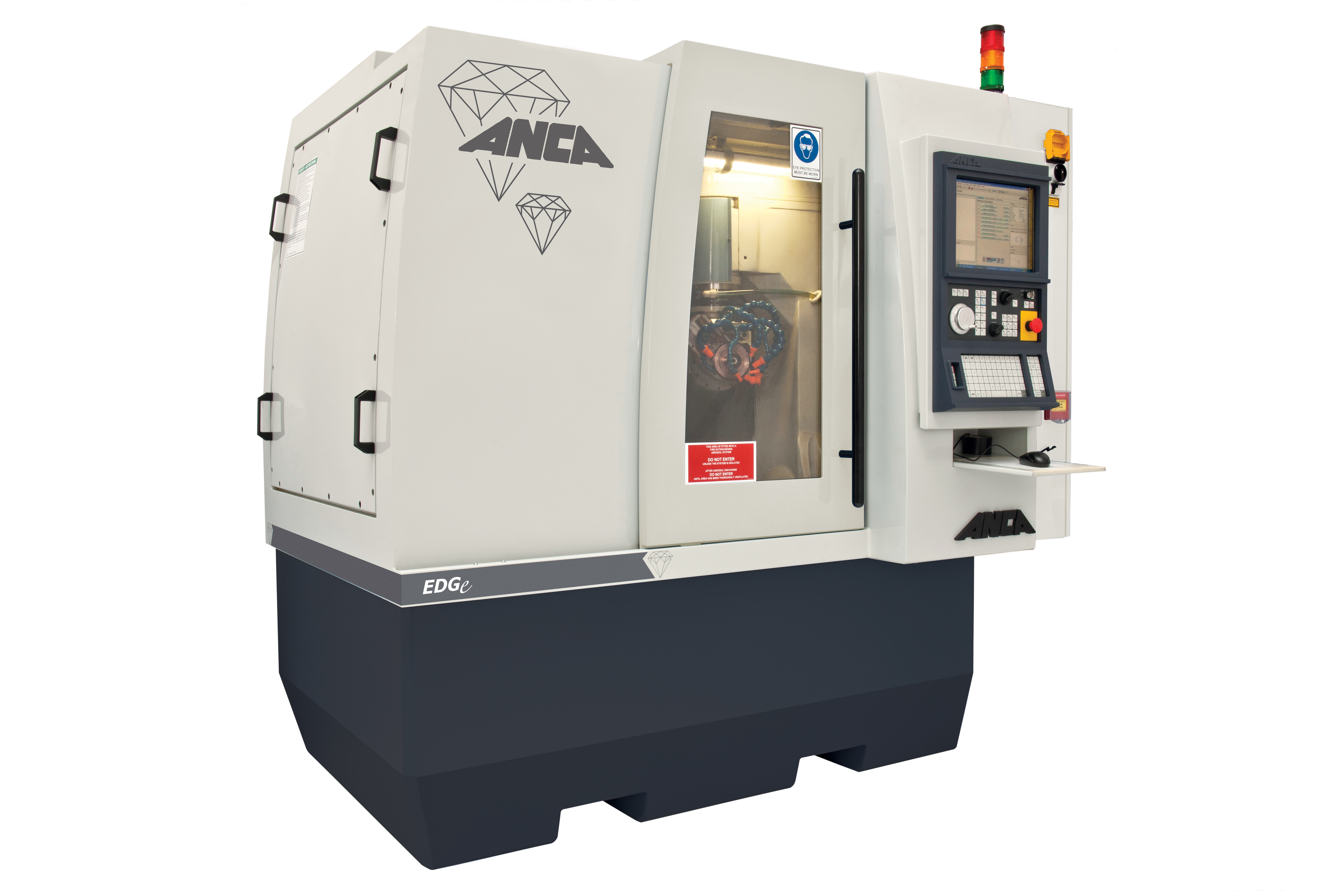
An ANCA EDGe machine used for PCD tool erosion.
Grinding with Variable Requirements
Duncan says: “Machining of these highly abrasive and non-homogenious materials requires careful consideration of the best tool for the job, be it drilling, trimming or pocketing. As a result, cutting tool manufacturers are continually creating new tool designs to meet this need.”
One of the most widely used composite materials is CFRP, principally due to its excellent strength to weight ratio and corrosion resistance. Yet, in machining this material, correct tool selection is critical, otherwise a variety of quality issues can result, including:
- Delamination, where the matrix separates from the fiber
- Uncut fibers that remain at the cut edge
- Spalling where larger fragments of matrix break away
- Inconsistent cut geometry can, for example, see hole roundness fall outside acceptable tolerances
- Hole exit burring when drilling
- Heat damage to the matrix
- Rapid tool wear
The consequences of these types of issues are wasted time and money from tools that rapidly wear out, but more importantly damaged or scrapped work pieces.
Today, ANCA machines are used by cutting tool manufacturers to create a variety of cutting tools for different composite machining applications.
ANCA’s ToolRoom software allows creation of unique tool geometries for CFRP cutting applications.
Tool Essentials for CFRP
Firstly, composite cutting tools come in one of three different material types. Carbide, coated carbide or PCD. Each has its advantages.
Carbide can be easily fashioned into any required geometry and will produce a keen cutting edge but will also be expected to wear quickly. For that reason, it will typically only get used in manual and/or roughing operations where the accuracy of the final cut is not critical – most likely because it will be followed by a finishing cutter made of either coated carbide or PCD.
Coated carbide similarly offers flexibility in that it can be ground into a variety of geometries, but has an additional (CVD) coating applied that can dramatically increase tool life. The disadvantage of these tools is that it is generally considered uneconomical to resharpen them.
The third class of tools is polycrystalline diamond (PCD) tools. The cutting edge on such tools are typically produced using an electro erosion machine, such as the ANCA EDGe, or laser ablation processes.
PCD insert brazed onto a carbide tool base. EDGe erosion process is used to generate an accurate corner radius profile.
This typically will give a keener cutting edge than CVD coated tools and additionally can be resharpened, which extends the usable life of the tool. Within PCD tools, there are three common forms. First, they can be a carbide base with brazed PCD inserts giving a shear cutting edge. This type of tool is commonly used to produce complex step or profile tools and is most easily produced by tool manufacturers looking to enter the PCD tool market.
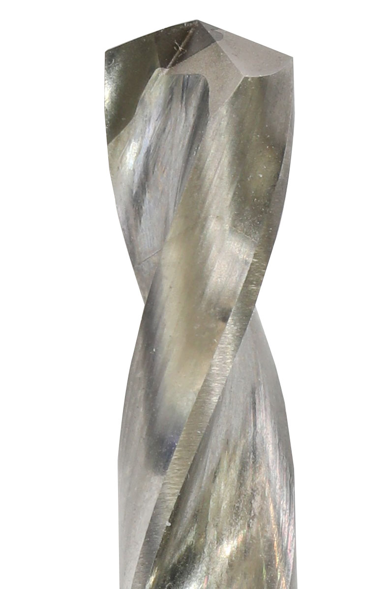
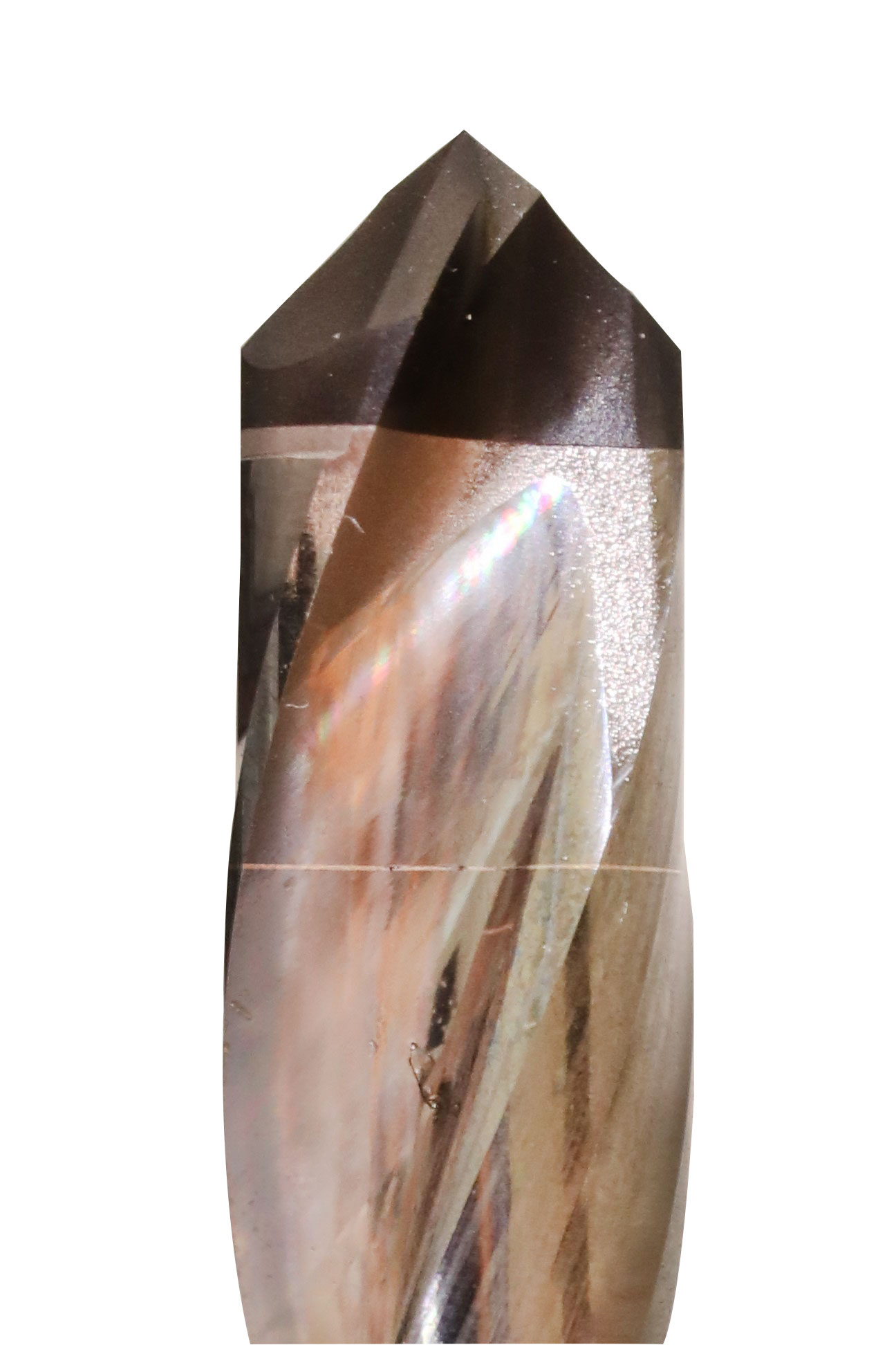
PCD vein is co-sintered with carbide, allowing generation of a helical cutting edge.
The next alternative is the veined PCD technology, initially developed in house by Sandvik Coromant Spanish Fork. This can create a helical vein of PCD, co-sintered in the carbide blank. The helical cutting edge is seen to offer an enhanced cutting geometry compared to that of a shear tool, and coolant holes can be included through the carbide portion, which improves cutting conditions. For these tools, the cutting edge geometry is largely defined by the PCD vein that was sintered.
The answer to this challenge is typically a solid PCD tip with a carbide body. While these can be expensive up front, RobbJack, based in California, produces such tools using rotary electro erosion process on the ANCA EDGe. This allows complete freedom for producing any tool (drill) geometry they require.
Solid PCD-tipped drills offer maximum flexibility in drill geometry for CFRP.
Hole Drilling CFRP
Hole drilling is a commonly performed operation necessary to allow joining of CFRP structures. CFRP drills will have a point geometry distinct to that of metalcutting drills. ANCA’s Toolroom software, whether applied to grinding or PCD erosion processes, allows creation of various special drill points suited to CFRP, including compound point angles and brad or W-point geometry. Specialized drill points result in minimised delamination as the drill penetrates through the CFRP layer, maintaining hole geometry (roundness) and offering superior tool life.
An alternative approach for holemaking is milling cutters used with interpolated orbital motion. While it’s a slower process requiring a CNC machine, it has advantages with creating larger holes or holes on curved surfaces. In addition, the smaller thrust force reduces delamination at the exit point of the hole.
Milling CFRP
Another common cutting operation is trimming or cutting of CFRP with specialised milling cutters. Again, coated carbide or PCD cutters are the order of the day.
For trimming or edge cuts, up-down cutters are most commonly used. The opposing direction of the cutting edges ensures cutting forces are toward the middle of the CFRP layer, thereby reducing the likelihood of delamination. Shallow flute depth helps increase tool rigidity.
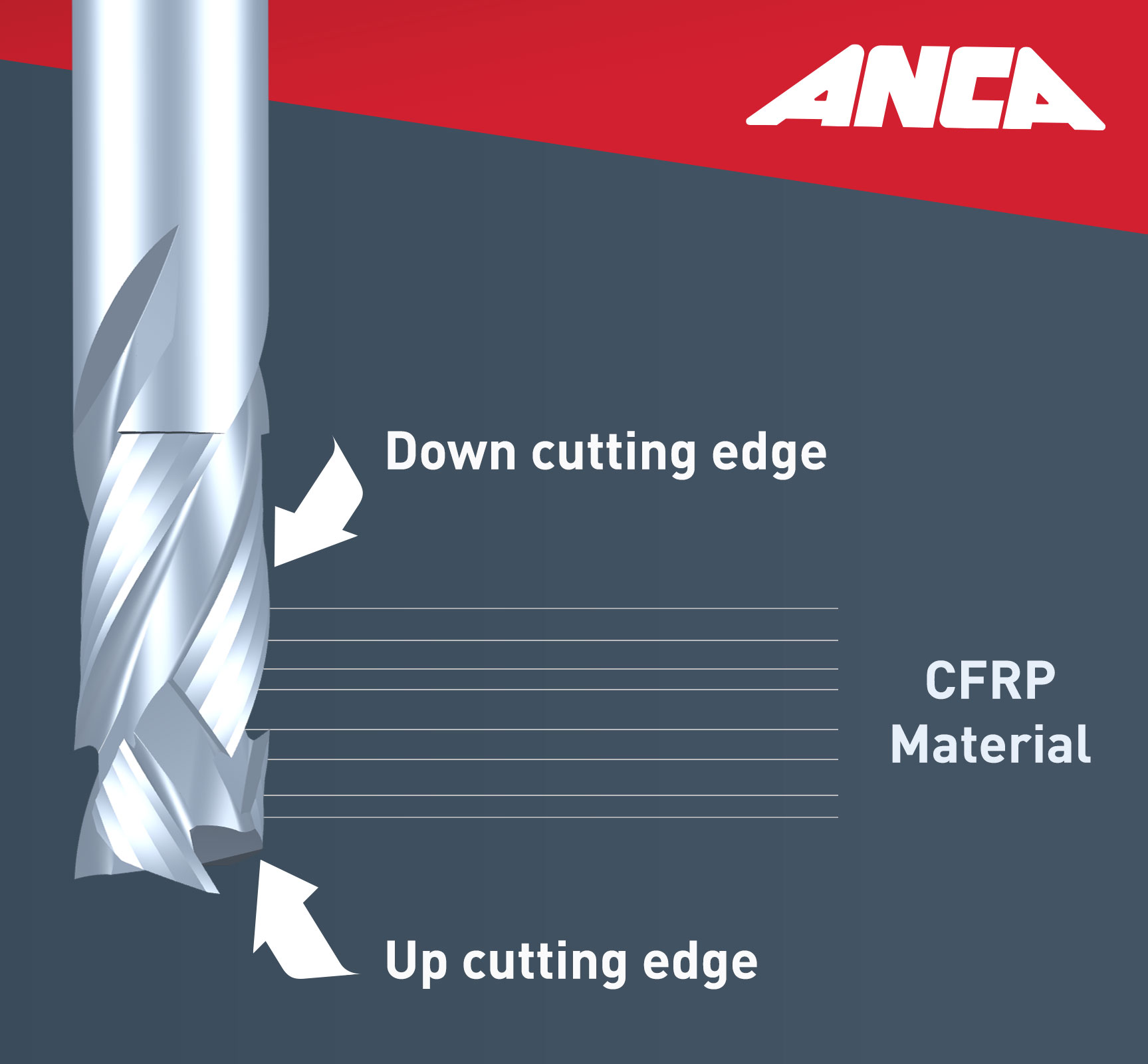
Compression cutters minimize damage to the CFRP cut edge with cutting forces toward the center of the CFRP layers.
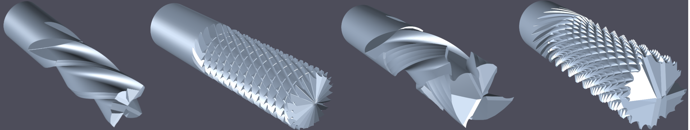
Burr style routers feature many shallow flutes that have chipbreaker teeth included on them. This form of cutter works to produce localized cutting forces that can effectively shear the fibers.
ANCA grinders support the manufacture of these types of tools with dedicated compression router or burr cutter software packages.
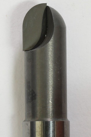
For surface or pocket milling, down-cut endmills again will create downward cutting forces that minimize surface delamination. Brazed PCD routers are also common for this application with ball or corner radius cutting edge forms, which are easily produced on the ANCA EDGe.
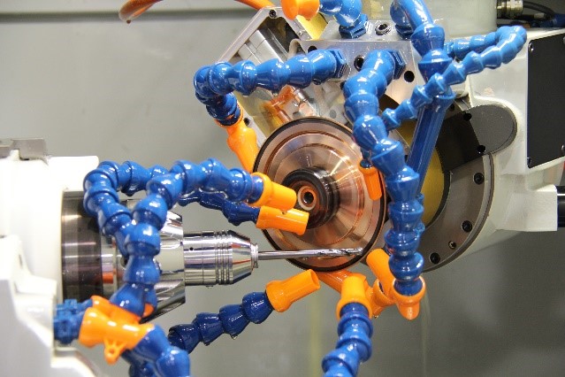
ANCA EDGe machine eroding a veined PCD drill from Sandvik Coromant.
