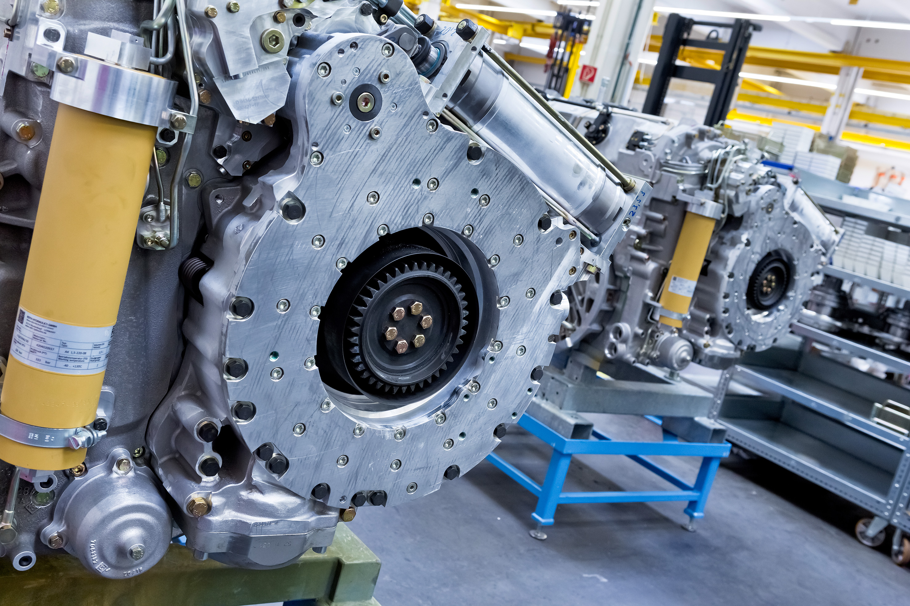
Unlike a car, a tracked armored vehicle can be driven, steered, and even braked all through its transmission. On vehicles kitted out by Renk, this braking effect is delivered by two different braking systems – one for low speeds, one for high speeds – working together using a mechanical brake in the lower speed range and a built-in hydrodynamic eddy-current brake known as a retarder.
Being responsible for changing gears, steering and braking, the transmission is essentially the central mobility unit of these vehicles and therefore plays a mission-critical role – and that's even before we consider that these 70-tonne monsters need to be extremely maneuverable at speeds of up 72 km/h on both roads and open terrain.
Renk is the global market leader in transmissions for tracked military vehicles weighing over 40 tons and supplies more than 40 armies around the world. Every transmission is designed for a specific type of vehicle and is specially adapted to suit the respective level of equipment and powertrain. In other words, Renk takes the respective basic transmission type and customizes it for its specific application in the vehicle.
The vehicle is steered by controlling the output speed via the final drive, then on the sprocket wheel drum, and then directly on the track itself. The driving direction can therefore only be influenced by changing the speeds of the individual tracks. Braking or accelerating is achieved by decreasing or increasing the track speeds at the same time. Different speeds at each of the tracks will steer the vehicle in one direction or another, or the vehicle will rotate around its vertical axis if the tracks run in opposing directions. All this – as well as the enormous forces that are generated as a result – must be handled by the transmission in every ambient condition imaginable. What's less surprising is that achieving this is dependent on a wide range of complex parts manufactured to stringent quality requirements.
The parts needed for the transmission are divided into three categories: housing parts, small cubic parts (force-carrying parts, valve blocks, brake parts, and fluid mechanics-related parts), and rotating parts with gear teeth for speed transmission. The latter is the typical parts installed in the powertrain of the transmission – and parts perfectly suited to complete machining on machines from WFL Millturn. There isn't a single part in this segment that is produced through turning alone as complex milled geometries and a range of holes are often also required. Rod and forged parts are predominantly made of high-strength steel from 1200 to 1300 N/mm2. "If it's round and has a gear cutting, it goes on a WFL machine," is the general rule.
"Typically, these parts are produced in small batch sizes of 1 to 300 units, whereby the average batch size is around 50 pieces," explains head of production Martin Wimmer. But parts for prototype transmissions in batch sizes of 1 to 5 units are also not unusual. Due to the flexibility of the sophisticated WFL machines, a separate prototype production line with different manufacturing processes is not required: even the smallest batch sizes can be produced extremely economically using the existing machinery. Cost-intensive special clamping devices are thereby rendered unnecessary, as workpieces are clamped on the Millturns by either standard jaws or a few special jaws with a three-jaw chuck.
A critical factor in determining the productivity of a machine is its programming, which is carried out exclusively using the Siemens NX CAD-CAM programming system. "For the first four WFL machines, we had different postprocessors due to the different machine models.
In the meantime, the PPs have been standardized so that every machine uses the same PP. The advantage here is that production can initially be planned independently of the machine. In other words, a program is created without having to know which machine it will ultimately be executed on. Only once the order is started will the Production Logistics team decide on which machine the respective parts will be produced," explains Wimmer.
The entire production process is simulated in the CAD-CAM, where the consistency of the data from the design of the parts to the production on the machine plays an important role. The CAM itself is a model of the machine, the chuck, clamping jaws, unfinished and finished parts, and the tools, which allows the reality to be simulated extremely accurately to ensure the programs tested work faultlessly in practice.
"This approach works well. Thanks to the comprehensive simulations we have practically no collisions anymore," summarizes Wimmer. The gear teeth are a certain exception during the simulation. Gear teeth are cut on the Millturns up to Module 4, which is predominantly special WFL cycles used for gear hobbing, as these can be applied very quickly and easily by entering the gear-cutting parameters.
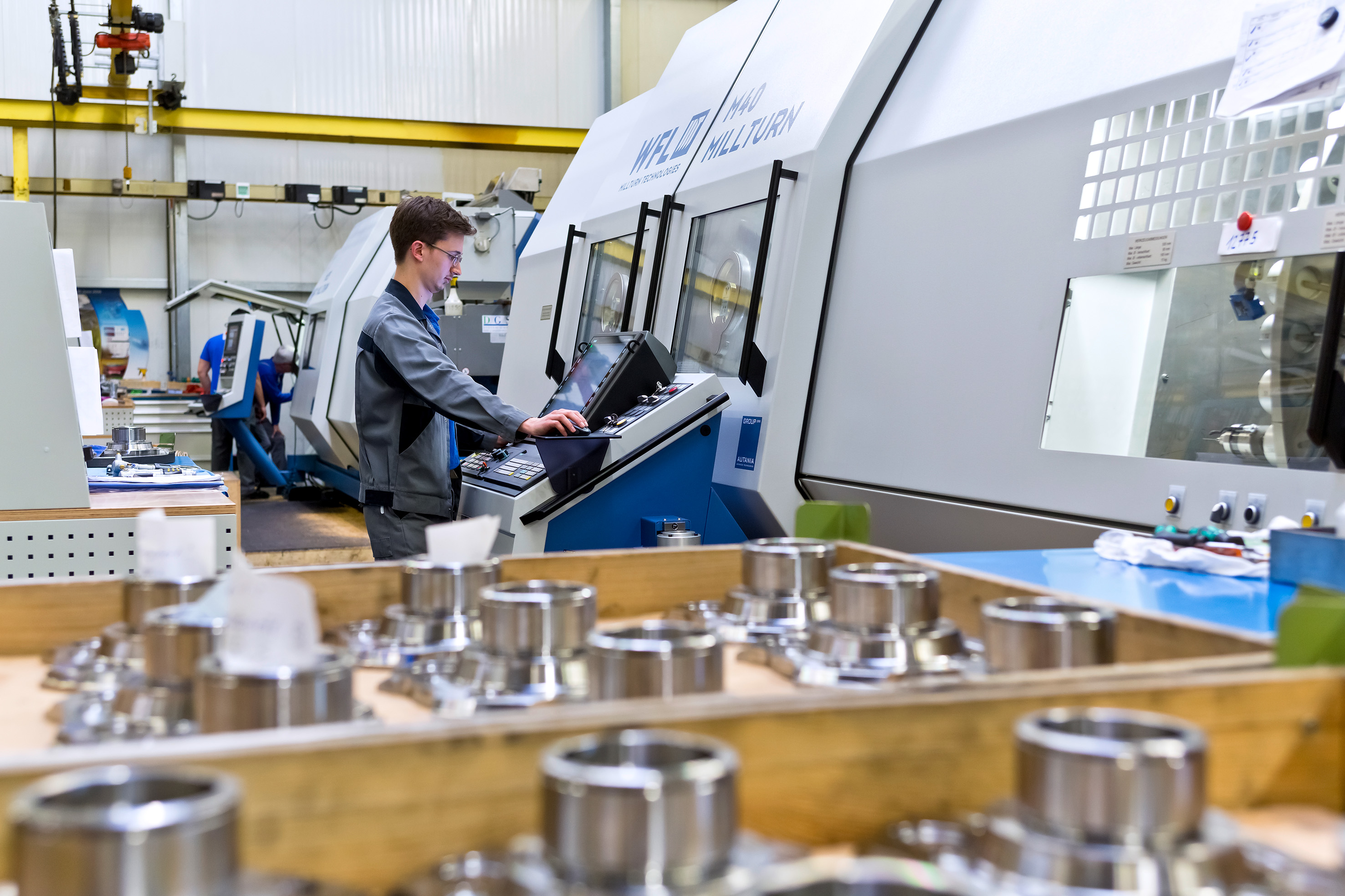
The first WFL Millturn was delivered in 2010 and Renk has been working intensively with complete machining ever since. "We analyzed our entire range of parts from the very small up to those with diameters of roughly 600 mm to standardize what was a very inhomogeneous machine park at the time. We wanted to have a machine concept that followed an identical structure for all parts of all sizes. WFL had the perfect offering for us with the M35 to the M50. In addition to turning, drilling, and milling on a single machine, it was important to us that the gear cutting – especially of Module 3 in Quality 8 – could be performed with a hobbing cutter clamped at one end.
While many manufacturers could promise this, only WFL delivered it. A positive impact in this respect is the extremely stable indexing of the B-axis with the large Hirth coupling in particular. The WFL-typical setup of the turning-boring-milling unit, whereby the milling spindle is designed as a high-torque gear spindle, ensures exceptionally high machining performance in all speed ranges.
The benefits of the extremely stable machine frame are not only measured in terms of productivity but ultimately the constant adherence to the tightest geometrical tolerances and the optimum surface qualities that are achieved," explains Wimmer on the varied technical reasons behind opting for WFL, before continuing to outline the clear benefits of Renk's decision:
"The machines are fitted with an 80 bar high-pressure coolant unit that can also be switched to air. In addition to the standard Capto C6 tool system, each machine is equipped with an extra, particularly stable tool accommodation on the turning-boring-milling unit. Heavy boring bars or special tools are securely held in place by a hydraulic prismatic tool accommodation.
Machines with a 3000 mm center distance also feature a built-in pick-up magazine for the automatic use of long boring bars in addition to the standard magazine.
"We no longer want to have to use different machines or external suppliers for the occasional special tasks," explained Wimmer. "Not only does this bring about a significant reduction in lead times, but the number of operations can be dramatically cut too. Individual operation sequences have been halved thanks to the complete machining. The combination machining has also allowed us to make savings in the runtime, with the capacity freed up through the more efficient use of our machine resources being used to perform additional work with the machine. For example, when the machining processes produce burrs, they are immediately deburred on the machine, improving productivity and safety while simultaneously minimizing the risk of injury. The user training from WFL has proven particularly helpful in this respect. As well as explaining how to program the machines, users were 3 given a detailed insight into the conceptual planning of the entire machining sequence as well as selecting the right clamping device. In the meantime, we now have nine WFL Millturns of three different sizes and two different turning lengths operating on our vehicle transmission production lines."
To boost efficiency and the level of utilization even further, the M35 delivered in 2017 was kitted out with an automation solution from FRAI Robotic Solutions, which has led to the more efficient production of workpieces such as planetary gears. An M40 has since been automated too. "We have exactly what we wanted: machines tailored precisely to our requirements that perfectly match our applications and space situation. With the second system we want to integrate a further turning station so that our staff can concentrate on demanding tasks," says Wimmer, delighted with the results of the investment.
Renk is especially well prepared for servicing and maintenance with its in-house maintenance team that takes care of small to medium repair tasks. "It was only right at the beginning that we had to learn that a tool change can take place at any length position and that you can sometimes find that there is a workpiece in the way, but that hasn't been an issue for a long time now," jokes Wimmer, looking back on those early days.
Machine data acquisition is a topic of growing importance at Renk. To this end, a system is already in use that displays the respective status of the machine via a dashboard. As it is important that the same solution can be used in every plant, Renk has opted for a universal solution that is not dependent on any one machine builder – and like with CAD-CAM, there is a close collaboration with Siemens here as well. Renk is already in a strong position about predictive maintenance and condition monitoring with its solutions: Renk Monitoring, which is also tried and tested with Renk transmissions, has been adapted for machine tools and forms the basis for this important future topic.
Contact Details
Related Glossary Terms
- boring
boring
Enlarging a hole that already has been drilled or cored. Generally, it is an operation of truing the previously drilled hole with a single-point, lathe-type tool. Boring is essentially internal turning, in that usually a single-point cutting tool forms the internal shape. Some tools are available with two cutting edges to balance cutting forces.
- chuck
chuck
Workholding device that affixes to a mill, lathe or drill-press spindle. It holds a tool or workpiece by one end, allowing it to be rotated. May also be fitted to the machine table to hold a workpiece. Two or more adjustable jaws actually hold the tool or part. May be actuated manually, pneumatically, hydraulically or electrically. See collet.
- computer-aided manufacturing ( CAM)
computer-aided manufacturing ( CAM)
Use of computers to control machining and manufacturing processes.
- coolant
coolant
Fluid that reduces temperature buildup at the tool/workpiece interface during machining. Normally takes the form of a liquid such as soluble or chemical mixtures (semisynthetic, synthetic) but can be pressurized air or other gas. Because of water’s ability to absorb great quantities of heat, it is widely used as a coolant and vehicle for various cutting compounds, with the water-to-compound ratio varying with the machining task. See cutting fluid; semisynthetic cutting fluid; soluble-oil cutting fluid; synthetic cutting fluid.
- gang cutting ( milling)
gang cutting ( milling)
Machining with several cutters mounted on a single arbor, generally for simultaneous cutting.
- milling
milling
Machining operation in which metal or other material is removed by applying power to a rotating cutter. In vertical milling, the cutting tool is mounted vertically on the spindle. In horizontal milling, the cutting tool is mounted horizontally, either directly on the spindle or on an arbor. Horizontal milling is further broken down into conventional milling, where the cutter rotates opposite the direction of feed, or “up” into the workpiece; and climb milling, where the cutter rotates in the direction of feed, or “down” into the workpiece. Milling operations include plane or surface milling, endmilling, facemilling, angle milling, form milling and profiling.
- turning
turning
Workpiece is held in a chuck, mounted on a face plate or secured between centers and rotated while a cutting tool, normally a single-point tool, is fed into it along its periphery or across its end or face. Takes the form of straight turning (cutting along the periphery of the workpiece); taper turning (creating a taper); step turning (turning different-size diameters on the same work); chamfering (beveling an edge or shoulder); facing (cutting on an end); turning threads (usually external but can be internal); roughing (high-volume metal removal); and finishing (final light cuts). Performed on lathes, turning centers, chucking machines, automatic screw machines and similar machines.