Article provided by CNC Software Inc.
After 9 years as a plant manager for a tool and die maker, Jason Cantrell decided to launch his own tool and die business. In 2011, he established Triple C Machine & Fab, Livingston, Tenn. Cantrell’s vision for business ownership has since paid off. What started as a small job shop has expanded into a thriving company.
“I decided to go out on my own so I bought a building and got started,” said Cantrell, Triple C President and owner. “Then it just grew from there — a lot more than I intended. And we’ll be growing even more.”
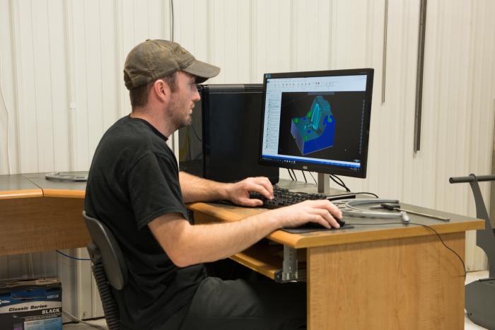
CNC programmer Josh Key programs OptiRough toolpaths to machine a form block for a die. All photos courtesy of CNC software
Steady growth led to Cantrell’s 2015 purchase of an additional building across town. The 30,000-sq.-ft. facility houses a metal stamping plant and will soon include additional CNC machine tools. Specializing in tool and die design, building and repair, as well as production machining, metal stamping and fabrication, Triple C has 22 employees, including four programmers and 10 shop-floor workers. CNC milling machines, lathes, and wire EDMs are used to machine A2, D2, DC53 and 4140 steel to serve the automotive, appliance, environmental and special machine industries. Once Triple C delved into 3D work, Cantrell knew it was time to investigate CAD/CAM software options.
“When you get into 3D machining, you find out quickly that software is a really important part of equipment,” he said. “We had to go with Mastercam (from CNC Software Inc., Tolland, Conn.). We do a lot of 3D machining, a lot of hard milling. It has really worked well for us.”
Triple C designs and manufactures a little bit of everything, according to Cantrell, in addition to production machine work. It relies on CAD/CAM software to program its milling machines and lathes.
“Most of our parts are for die/stamping,” said Josh Key, Triple C CNC programmer. “We make details and sections for these dies for local facilities. That’s where we use Mastercam the most.”
With short lead times and a constant full workload, Triple C pushes its CNC machines to optimal speeds by programming toolpaths with the software’s Dynamic Motion technology for high speed milling. Dynamic Motion technology relies on proprietary algorithms programmed into the software that detect changes in the material as the tool moves through. By utilizing the entire flute length of cutting tools, air cutting is minimized or eliminated entirely, saving wear and tear on the tools and ensuring constant chip loading.
“When we began using the high speed toolpaths, it really changed a lot for me,” Key said. “We could then use the full length of our flutes on solid carbide and get so much less air cut. Everybody back then seemed to be using contoured toolpaths for depth cuts. The high-speed toolpaths changed everything.”
The folks at Triple C repeatedly rely on some of their favorite features in the software to produce more complex parts, but with ever-shortening lead times.
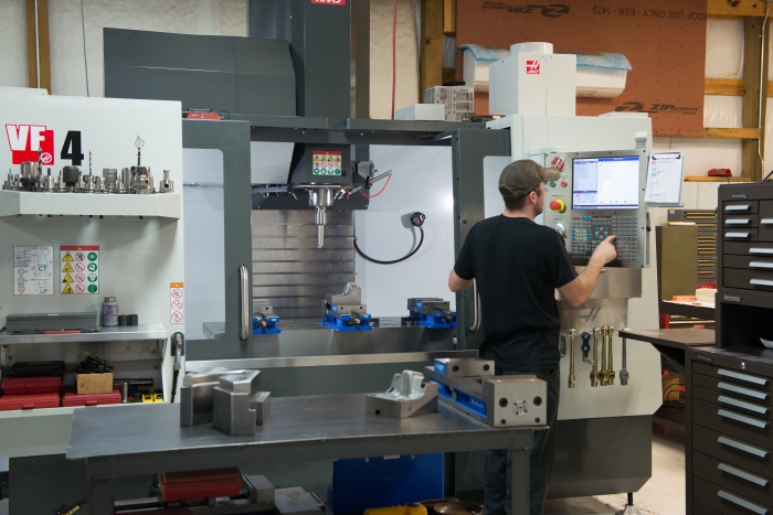
Josh Key sets up a CNC mill to machine a form block.
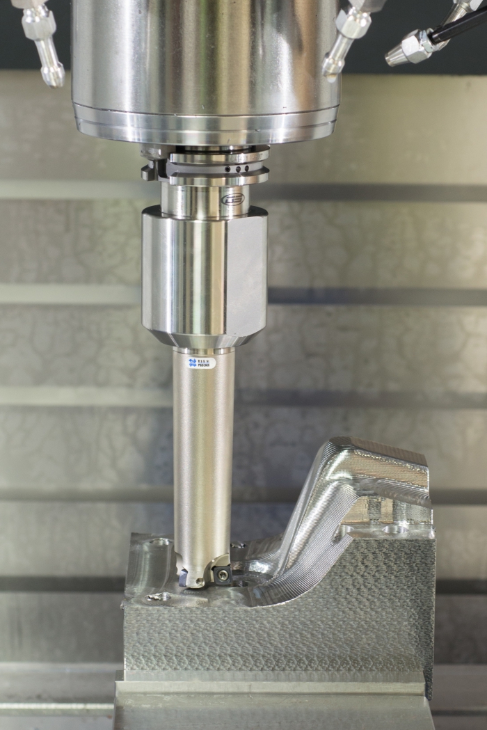
According to Key, the OptiRough toolpath is one of the most beneficial features of Mastercam, especially in the machining of complex die parts. Operators can rough out parts efficiently because OptiRough removes large amounts of material, resulting in a fully roughed part made in less time than if made using traditional roughing methods. The toolpath supports using high feed cutters. A single Dynamic OptiRough toolpath can cut material in two directions: on stepdowns (-Z) and stepups (+Z). The bi-directional technology uses the minimum amount of stepdowns, for reduced cycle times.
“We use a lot of high feed cutters and the OptiRough toolpath to get our parts roughed out,” Key said. “And we like using the 3D Hybrid and Scallop high-speed toolpaths. The toolpaths keep our tools in constant motion with chips flying. There’s not a lot of air cutting, no wasted time. They really keep our cutting tools engaged.”
Triple C does not regularly machine large part runs; in one day, one operator may produce five parts, all completely different. Though quantifying time and dollar savings is difficult, recognizing overall improvements like tool performance and increased cutting speed is not.
“We’re a job shop and everything we do is different,” Key said. “With the software, I know that I can get more out of my tools—longer tool life and faster cycle times. I have less chatter and better finishes. Those are the kind of results I see.”
With short lead times and a constant full workload, Triple C pushes its CNC machines to optimal speeds by programming toolpaths with the software’s Dynamic Motion technology for high speed milling.
For Triple C customers who do not submit solid models of their parts, designers use the Solids feature to design and turn customer CAD drawings into solid model Mastercam files. Designers and programmers can mix and match several modeling techniques, adding surface or wireframe elements to the model, cutting down on programming time.
“I really enjoy drawing and designing in Mastercam,” Key said. “I like how I can design and do my drawing right there, and then do the work for the part all in the same place.”
“Sometimes stamping customers will provide 3D models of what they need,” Cantrell said. “We take their models and make our machining programs from them. The software has helped us with this because before, we could never get the surface finish tolerances close enough. We had to spend a lot of time polishing. Now we can finish the part on the mill.”
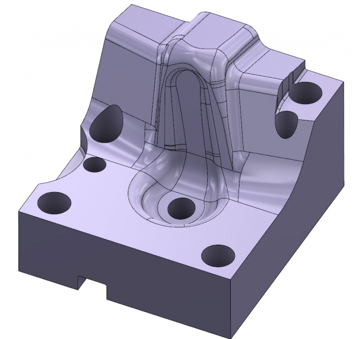
Triple C runs Mastercam Machine Simulation on 3D parts to check for gouges and ensure proper tool engagement. Once the simulation is complete and the process is verified, operators load the part and program and start the cutting process. While the machine tool is running, the operator is free to move on to another project, saving valuable time.
“The simulation program has really helped us,” Key said. “If the machine is going to run for3 or 4 hours by itself, we can verify the process on the computer. The operator does not have to watch over it.
Triple C started with one seat of CAD/CAM software has and now has five, which proves especially helpful when a customer breaks a die or a part. Employees are able to replace or repair multiple pieces at the same time. For a company that must complete each incoming job within a week or two, timing is critical.
“We’ve got the capacity for each of us to be working on a different piece of the puzzle, or for a different customer,” said Key. “We don’t have a lot of lead time here. Everything has to be flipped quickly, so having multiple guys programming lets us take on more work.”
With the continued help of Mastercam’s high speed toolpaths, simulation, and process control capabilities, Triple C will be able to take on those jobs and then some.
“Our line of work is so competitive,” said Cantrell. “We have new machines, new software, and great people. As long as we maintain that, I think we’ll stay busy.”
Related Glossary Terms
- chatter
chatter
Condition of vibration involving the machine, workpiece and cutting tool. Once this condition arises, it is often self-sustaining until the problem is corrected. Chatter can be identified when lines or grooves appear at regular intervals in the workpiece. These lines or grooves are caused by the teeth of the cutter as they vibrate in and out of the workpiece and their spacing depends on the frequency of vibration.
- computer numerical control ( CNC)
computer numerical control ( CNC)
Microprocessor-based controller dedicated to a machine tool that permits the creation or modification of parts. Programmed numerical control activates the machine’s servos and spindle drives and controls the various machining operations. See DNC, direct numerical control; NC, numerical control.
- computer-aided design ( CAD)
computer-aided design ( CAD)
Product-design functions performed with the help of computers and special software.
- cutting speed
cutting speed
Tangential velocity on the surface of the tool or workpiece at the cutting interface. The formula for cutting speed (sfm) is tool diameter 5 0.26 5 spindle speed (rpm). The formula for feed per tooth (fpt) is table feed (ipm)/number of flutes/spindle speed (rpm). The formula for spindle speed (rpm) is cutting speed (sfm) 5 3.82/tool diameter. The formula for table feed (ipm) is feed per tooth (ftp) 5 number of tool flutes 5 spindle speed (rpm).
- feed
feed
Rate of change of position of the tool as a whole, relative to the workpiece while cutting.
- flutes
flutes
Grooves and spaces in the body of a tool that permit chip removal from, and cutting-fluid application to, the point of cut.
- gang cutting ( milling)
gang cutting ( milling)
Machining with several cutters mounted on a single arbor, generally for simultaneous cutting.
- milling
milling
Machining operation in which metal or other material is removed by applying power to a rotating cutter. In vertical milling, the cutting tool is mounted vertically on the spindle. In horizontal milling, the cutting tool is mounted horizontally, either directly on the spindle or on an arbor. Horizontal milling is further broken down into conventional milling, where the cutter rotates opposite the direction of feed, or “up” into the workpiece; and climb milling, where the cutter rotates in the direction of feed, or “down” into the workpiece. Milling operations include plane or surface milling, endmilling, facemilling, angle milling, form milling and profiling.
- milling machine ( mill)
milling machine ( mill)
Runs endmills and arbor-mounted milling cutters. Features include a head with a spindle that drives the cutters; a column, knee and table that provide motion in the three Cartesian axes; and a base that supports the components and houses the cutting-fluid pump and reservoir. The work is mounted on the table and fed into the rotating cutter or endmill to accomplish the milling steps; vertical milling machines also feed endmills into the work by means of a spindle-mounted quill. Models range from small manual machines to big bed-type and duplex mills. All take one of three basic forms: vertical, horizontal or convertible horizontal/vertical. Vertical machines may be knee-type (the table is mounted on a knee that can be elevated) or bed-type (the table is securely supported and only moves horizontally). In general, horizontal machines are bigger and more powerful, while vertical machines are lighter but more versatile and easier to set up and operate.
- payload ( workload)
payload ( workload)
Maximum load that the robot can handle safely.
- polishing
polishing
Abrasive process that improves surface finish and blends contours. Abrasive particles attached to a flexible backing abrade the workpiece.
- process control
process control
Method of monitoring a process. Relates to electronic hardware and instrumentation used in automated process control. See in-process gaging, inspection; SPC, statistical process control.
- solid model
solid model
3-D model created using “building blocks.” This is the most accurate way of representing real-world objects in CAD.
- toolpath( cutter path)
toolpath( cutter path)
2-D or 3-D path generated by program code or a CAM system and followed by tool when machining a part.