Article from Siemens Industry Inc.
DMG Mori manufactures a wide variety of conventional chip-cutting machining centers for OEMs and production job shops that serve the demanding oil-and-gas industry. Inherent in this market are several factors that lobby for great care and planning in the machining process. Typically, components produced for the oil-and-gas field are large, heavy and often have complex contours, making the machining time long and the tool life short. The DMU 50, although an entry-level 5-axis machining center from DMG Mori, is a compact unit that features considerable strength.
“It is a David handles Goliath type of story,” says Matthias Leinberger, the business development director for Siemens PLM (Product Lifecycle Management).
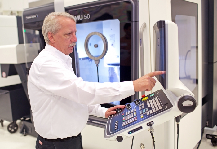
A DMG employee showcasing the DMU 50 with Siemens' 840D sl CNC. The features of the 840D allow a streamlined simulation of the actual cutting path.
On one recent application, DMG Mori was challenged with a 440-lb., 8” diameter x 8” high workpiece made from 1045 grade steel and being machined into a rock bit for oil field exploration. The customer further presented the builder with the need for fast changeover to produce the part from various metal materials, with all the attendant tool changes and workpiece setup variances present. The customer, a major upstream oil industry supplier, was trying to decide if the better path for this product was a single block of steel or a near net casting being machined. Both high-speed roughing and then precise 5-axis machining were required in this small footprint machine, which had been selected by the customer due to specific plant capacity utilization concerns, plus their desire for a flexible, reasonably priced and highly cost-effective machine tool.
The machine builder turned to its longtime business partner, Siemens, for assistance. By offering a total package of CAD-CAM-CNC hardware, software and engineering services, Siemens was able to help the machine builder substantially improve every aspect of part production, including reduction of design-to-part protocols, machining time, tool life, surface finish, dimensional accuracies and overall production efficiencies. This scenario was particularly applicable in this case, as the production runs were anticipated to be low with short lead times.
Starting from the CAD file, the Siemens PLM team ran the program through its NX CAM process, eliminating the setups through full 5-axis operation. The User Defined Events (UDEs) feature inside the NX program allows simple check boxes for triggering post-processors references for coolant pressure, spindle speed settings and more. This avoids manual programming and, as a result, reduced the program transition time from as long as two days to approximately 30 minutes.
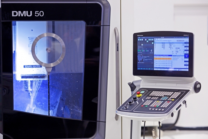
Close up of the DMU 50 with Siemens' 840D sl CNC.
Once the program was ready for the CNC, the features of that control allowed a more streamlined simulation of the actual cutting path. The 3D quick set compressor feature provides a parametric itemized data file for all path motions, thereby eliminating collision and ensuring the optimal toolpath, in conjunction with the NC kernel and PLC on the machine tool.
As Randy Pearson, Siemens technical applications center manager, observes, “This feature is a huge time saver for our customer, as the test ball and probe in the spindle mechanism can be run at any point in the cycle, testing the actual machine kinematics at any time. The procedure can also be automated to run on the table at prescribed time intervals.”
The high-speed machining feature is highlighted here by Cycle 800, which is a static plane transformation that allows a 5-axis machine to define a rotated working plane in space. It is commonly known in the trade as 3+2 programming. The cycle converts the actual workpiece zero and tool offsets to refer to the rotated surface. Of note here, the cycle accommodates particular machine kinematics and positions the physical axes normal to the working plane. This is referenced as TRAORI or transformation orientation.
Meanwhile, Sinumerik Operate, the CNC’s easy-to-use, graphical user interface on the machine allows the operator to perform a variety of integrated tool management and information management functions, all transportable on a USB or network connection.
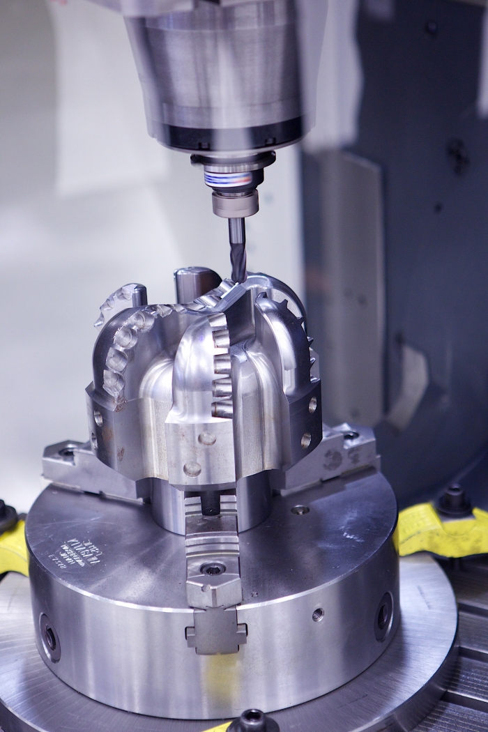
An oil field rock bit being machined on a DMU 50 with Siemens 840D sl CNC. Both high-speed roughing and precise 5-axis machining are possible on this small footprint, entry-level machine.
In the simulation, the loading and fixturing of the workpiece is performed virtually in the NX CAM program, which also calculates a consistent chip load, critical in these large material-removal applications. The simulation further verifies the tool length at all cutting sections and the program is finalized for the machine to begin.
In production, this process also yielded a substantial improvement in tool life on this heavy part over the 3-¾ hour cycle time, according to DMG National Product Manager Luke Ivaska. “With the combination of the NX CAM software, plus the CNC on the machine and all it could do, we had some initial challenges, as most software programs are purpose-built CAM packages that allow quick and easy use by anyone. They have significant limitations; however, as the software drives the toolpath and the operator has very little control. With NX and Sinumerik CNC, we have a lot more input on the creation of the toolpath. I have yet to find a problem I could not solve with NX.”
In the CNC, the Sinumerik Operate affords the end user’s operator and manufacturing engineering personnel full access to a variety of conditions in production, including all roughing and finishing data in plain text, plus all 5-axis transformation orientation data logged for restart after any interruption and manual restart.
Easy-to-use probing for work offsets is another advantage the builder and their customer enjoy with the CNC used on this machine. The operator is guided graphically for setting the workpiece zero, for example, while the tool length is automatically included in the calculation. With the Operate system, the difference between the position value in the machine coordinate system and workpiece coordinate system is saved in the active zero offset.
The variable streamline operation of the machine tool combines here with an interpolated vector to produce a smoother finish in the machining of the intricate rock bit surfaces in a single toolpath. The machine seamlessly transitions from square-to-round machining and then the extreme angle paths needed to accurately machine the internal surfaces. A single bit portion of the program is automatically captured, so a step-and-repeat program can be built-up. The simulation of each bit cutting path was done on both the NX CAM and the CNC programs. It is literally like working with a “digital twin” of the machine.
This vectored program, it should be noted, is transportable to any machine with comparable results, according to Pearson and Leinberger, who comments, “Precisely because the machine kinematics are knowable, this program, once created, can be transferred onto multiple machines within the same facility or run by shops around the world, all tied together by the control, so there is total continuity between the operations, the data capture protocol and feedback received for production analysis.”
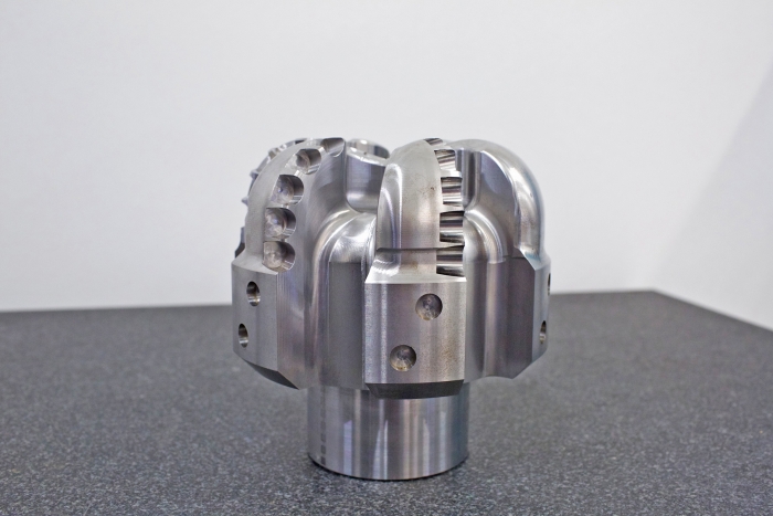
An 8"x8" rock bit machined from 1045 grade steel on the DMU 50. Speedy setup and machining was made possible with Siemens' package of CAD-CAM-CNC hardware.
Pearson further noted that, in this application, the customer’s desire to change the materials used on successive runs could be easily accommodated by the control, owing to its ability for on-the-fly adjustments, based on the orientation of the tool tip to the workpiece.
This project was accomplished, using CELOS onboard the DMG Mori machine. CELOS facilitates the total interaction between operator and machine, in this application, as it has numerous apps to enable instant call-up of actual conditions, full data comparison through a link to CAD and CAM products, plus full interface to the customer company’s ERP system for logging and analysis, with in-process remote adjustments achievable. In the case of this oil-and-gas customer, interactive communication to a global production network is also provided, which allow the customer to run parallel production of different rock bits at locations around the world, with seamless data tracking and full production analysis.
Related Glossary Terms
- centers
centers
Cone-shaped pins that support a workpiece by one or two ends during machining. The centers fit into holes drilled in the workpiece ends. Centers that turn with the workpiece are called “live” centers; those that do not are called “dead” centers.
- computer numerical control ( CNC)
computer numerical control ( CNC)
Microprocessor-based controller dedicated to a machine tool that permits the creation or modification of parts. Programmed numerical control activates the machine’s servos and spindle drives and controls the various machining operations. See DNC, direct numerical control; NC, numerical control.
- computer-aided design ( CAD)
computer-aided design ( CAD)
Product-design functions performed with the help of computers and special software.
- computer-aided manufacturing ( CAM)
computer-aided manufacturing ( CAM)
Use of computers to control machining and manufacturing processes.
- coolant
coolant
Fluid that reduces temperature buildup at the tool/workpiece interface during machining. Normally takes the form of a liquid such as soluble or chemical mixtures (semisynthetic, synthetic) but can be pressurized air or other gas. Because of water’s ability to absorb great quantities of heat, it is widely used as a coolant and vehicle for various cutting compounds, with the water-to-compound ratio varying with the machining task. See cutting fluid; semisynthetic cutting fluid; soluble-oil cutting fluid; synthetic cutting fluid.
- machining center
machining center
CNC machine tool capable of drilling, reaming, tapping, milling and boring. Normally comes with an automatic toolchanger. See automatic toolchanger.
- numerical control ( NC)
numerical control ( NC)
Any controlled equipment that allows an operator to program its movement by entering a series of coded numbers and symbols. See CNC, computer numerical control; DNC, direct numerical control.
- parallel
parallel
Strip or block of precision-ground stock used to elevate a workpiece, while keeping it parallel to the worktable, to prevent cutter/table contact.
- toolpath( cutter path)
toolpath( cutter path)
2-D or 3-D path generated by program code or a CAM system and followed by tool when machining a part.