Article from DP Technology
Burr Oak Tool Inc. is a leading producer of dies used to produce two types of fins for window air conditioners. Evaporator fins on the side of the air conditioner inside the window transfer heat from the inside air to the cold refrigerant flowing through the evaporator coil. Compressor fins located on the side of the air conditioner outside the window move heat from the now hot refrigerant to the outside air. Burr Oak Tool dies progressively stretch and reform the fins through a series of metal forming operations that extrude and reduce the thickness of the fins. The complex geometry of the dies must be controlled within +0.0005"/-0.0000" to meet fin tolerances.
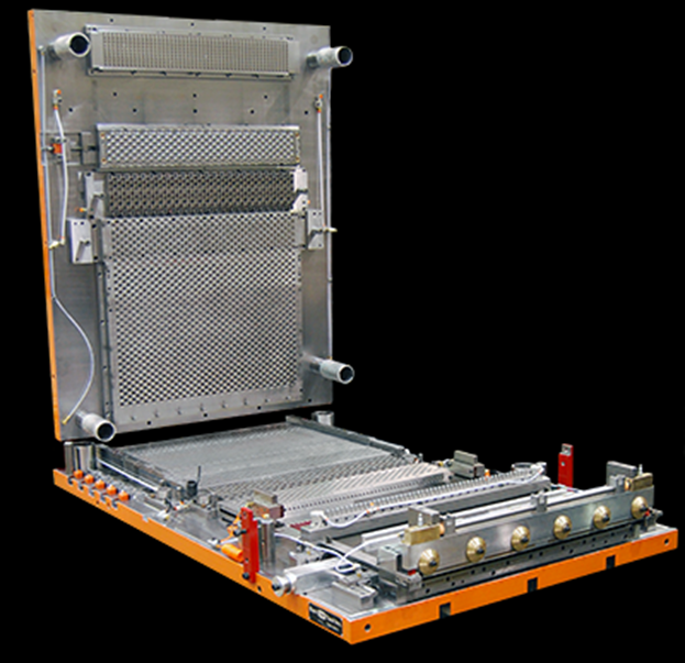
A completed fin die.
Until recently, the company finished and semifinished form plates on a form grinder because its machining centers could not hold the required tolerances. It took 9.2 hours to produce form plates with a waffle form and 11.3 hours for sine wave form plates. The company recently purchased a Mazak VTC-800 4-axis vertical machining center with the goal of reducing machining time for these dies. The new machine is much more difficult to program than any of the machines used previously by the company. Adding to the challenge is the fact that parts are designed in 2D because they have so many holes and other features that it would take prohibitively long to design them as solid models.
Back in the mid-1990s, Burr Oak Tool used a CAM software package that did not accurately simulate machining operations. The company mounted many of the parts it machined on workholding devices called tombstones and it was not unusual for a spindle driven by a new program to crash into a tombstone, which often required expensive repairs.
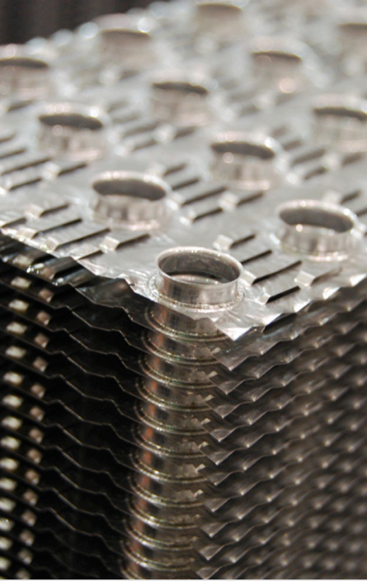
Fins produced on dies from Burr Oak Tool.
“We switched to Esprit CAM software from DP Technology because it accurately simulates the machine, spindles, tools and workpiece in real-time operation,” said David Schwartz, CNC programming manager for Burr Oak Tool. After the purchase of a new 4-axis machining center, Burr OAK Tool programmers attended Esprit training for the Mazak VTC-800 and the company purchased a Solid Mill Free-Form 3-axis add-on for one of its Esprit licenses.
With the CAM software, Burr Oak Tool programmers detect crashes and gouges during the programming process before downloading the program to the machine. Esprit’s simulation capabilities have eliminated crashes while substantially improving the productivity of the company’s programming team. Over the time it has used Esprit, the company has reduced its programming team from 13 to six people through innovation while substantially increasing its programming volume and capabilities.
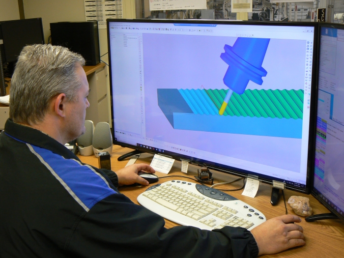
Simulating a machining operation with Esprit CAM software.
The first step in programming the form plate is importing the 2D models that contain the part definition. Only a few clicks are needed to extrude the 2D models to create the 3D surface geometry. The next step is to define features such as holes and bosses which map into machining operations. Burr Oak Tool programmers currently perform this step manually although in the future they plan to investigate the automatic feature recognition capability of Esprit. Burr Oak Tool programmers use the software’s mill between curves feature to define the surface to be milled.
Most machining operations are performed with the spindle tilted at 30º with respect to the workpiece because ballnose endmills perform better when cutting on their sides than on their points. The milling operation is typically run at a 250-ipm feed rate and produces an 8 Ra finish, which matches or even exceeds the finish produced by grinding. This new procedure works so well, they were able to eliminate a separate roughing operation on the vertical machine centers and go directly to a tilted head semifinishing operation on the VTC-800 that leaves only 0.002" for finishing with a small ballnose endmill.
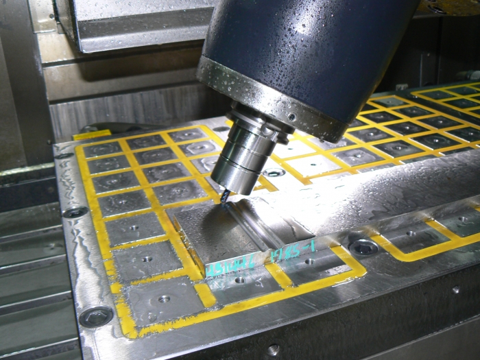
Machining of fin die on a Mazak vertical machining center.
Esprit simulation automatically identifies any moves where the spindle or tool passes too close to the part or machine. Programmers closely compare the simulation results to make sure it matches the design spec. As a final step, programmers use the Esprit post-processor for the Mazak VTC-800 to produce code that runs perfectly every time. Thanks to its accurate simulation and code, Burr Oak Tool programmers feel confident enough to run lights-out even with high precision, single run, custom parts.

David Schwartz, CNC programming manager at Burr Oak Tool: "We switched to Esprit because it accurately simulates the machine, turrets, spindles, tools, and workpiece in real-time operation."
“We have reduced machining time to three hours on the waffle dies and four hours on the sine wave dies, substantially reducing the cost of producing these critical tools,” Schwartz concluded. “Programming the form milling operations on the dies takes only about two hours, which is remarkably low considering the complexity of the part. We are confident that once we fully incorporate the capabilities of Esprit into our programming methodology we will be able to reduce fin die programming time to only one hour.”
Contact Details
Related Glossary Terms
- burr
burr
Stringy portions of material formed on workpiece edges during machining. Often sharp. Can be removed with hand files, abrasive wheels or belts, wire wheels, abrasive-fiber brushes, waterjet equipment or other methods.
- centers
centers
Cone-shaped pins that support a workpiece by one or two ends during machining. The centers fit into holes drilled in the workpiece ends. Centers that turn with the workpiece are called “live” centers; those that do not are called “dead” centers.
- computer numerical control ( CNC)
computer numerical control ( CNC)
Microprocessor-based controller dedicated to a machine tool that permits the creation or modification of parts. Programmed numerical control activates the machine’s servos and spindle drives and controls the various machining operations. See DNC, direct numerical control; NC, numerical control.
- computer-aided manufacturing ( CAM)
computer-aided manufacturing ( CAM)
Use of computers to control machining and manufacturing processes.
- endmill
endmill
Milling cutter held by its shank that cuts on its periphery and, if so configured, on its free end. Takes a variety of shapes (single- and double-end, roughing, ballnose and cup-end) and sizes (stub, medium, long and extra-long). Also comes with differing numbers of flutes.
- feed
feed
Rate of change of position of the tool as a whole, relative to the workpiece while cutting.
- gang cutting ( milling)
gang cutting ( milling)
Machining with several cutters mounted on a single arbor, generally for simultaneous cutting.
- grinding
grinding
Machining operation in which material is removed from the workpiece by a powered abrasive wheel, stone, belt, paste, sheet, compound, slurry, etc. Takes various forms: surface grinding (creates flat and/or squared surfaces); cylindrical grinding (for external cylindrical and tapered shapes, fillets, undercuts, etc.); centerless grinding; chamfering; thread and form grinding; tool and cutter grinding; offhand grinding; lapping and polishing (grinding with extremely fine grits to create ultrasmooth surfaces); honing; and disc grinding.
- machining center
machining center
CNC machine tool capable of drilling, reaming, tapping, milling and boring. Normally comes with an automatic toolchanger. See automatic toolchanger.
- milling
milling
Machining operation in which metal or other material is removed by applying power to a rotating cutter. In vertical milling, the cutting tool is mounted vertically on the spindle. In horizontal milling, the cutting tool is mounted horizontally, either directly on the spindle or on an arbor. Horizontal milling is further broken down into conventional milling, where the cutter rotates opposite the direction of feed, or “up” into the workpiece; and climb milling, where the cutter rotates in the direction of feed, or “down” into the workpiece. Milling operations include plane or surface milling, endmilling, facemilling, angle milling, form milling and profiling.
- milling machine ( mill)
milling machine ( mill)
Runs endmills and arbor-mounted milling cutters. Features include a head with a spindle that drives the cutters; a column, knee and table that provide motion in the three Cartesian axes; and a base that supports the components and houses the cutting-fluid pump and reservoir. The work is mounted on the table and fed into the rotating cutter or endmill to accomplish the milling steps; vertical milling machines also feed endmills into the work by means of a spindle-mounted quill. Models range from small manual machines to big bed-type and duplex mills. All take one of three basic forms: vertical, horizontal or convertible horizontal/vertical. Vertical machines may be knee-type (the table is mounted on a knee that can be elevated) or bed-type (the table is securely supported and only moves horizontally). In general, horizontal machines are bigger and more powerful, while vertical machines are lighter but more versatile and easier to set up and operate.

