Understanding tool wear is the first step to extending tool life—which can be further enhanced with new coating technology.
Tool wear is one of the most basic propositions of machining. Defining and understanding it can help toolmakers and users extend tool life. Also, today’s tool coating technology, including new alloying elements, provides a means to extend tool life further while improving productivity.
Wear Elements
Energy is an expression of the heat and friction that develop during metalcutting. Heat and friction—produced by high surface loads and from chips sliding at high speed along the tool rake face—subject cutting tools to extremely challenging conditions.
Cutting forces tend to fluctuate depending on conditions such as the presence of hard inclusions in the workpiece or during interrupted cutting. Therefore, cutting tools require several characteristics to maintain strength at high temperatures, including extreme toughness, wear resistance and high hardness.
Courtesy of All Images: Iscar Metals
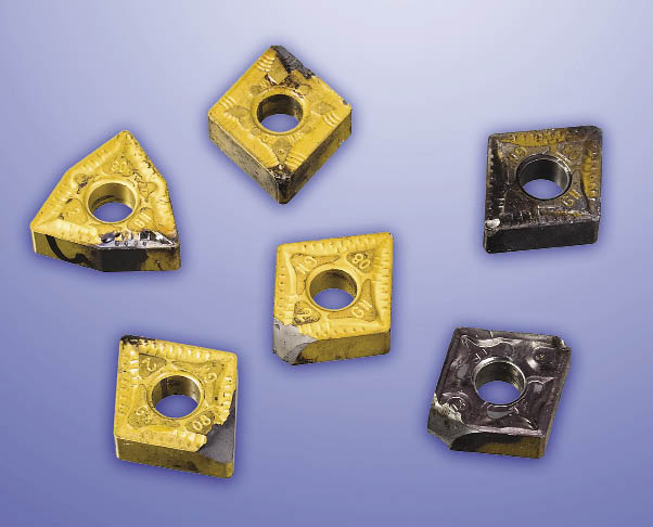
Inserts showing extensive wear; they are no longer usable for cutting metal.
While temperature at the tool/workpiece interface is a key factor in the wear rate of virtually all tool materials, it is difficult to establish values for the parameters required for calculating the temperature. However, experimental measurements can provide the basis for empirical approaches.
It is commonly assumed that the energy generated when cutting is converted to heat and 80 percent of that heat is typically carried away in the chip (this varies based on several factors—particularly the cutting speed). This leaves about 20 percent of the heat going into the cutting tool. Even when cutting mild steel, tool temperatures can exceed 550° C, the maximum temperature HSS can withstand without losing hardness. Cutting hard steels with PCBN tools will typically result in tool and chip temperatures exceeding 1,000° C.
Tool Wear and Tool Life
Several types of tool wear exist, including:
• flank,
• notch,
• crater,
• edge rounding,
• edge chipping,
• edge cracking, and
• catastrophic failure.
There is no universally accepted definition of tool life, which is typically based on the workpiece and tool materials and cutting processes. One way of quantifying an end point for tool life is to put a limit on the maximum acceptable flank wear, known as VB or VBmax. Tool life can be expressed in the Taylor equation for tool life expectancy:
VcTn = C
A more commonly used form of the equation is:
VcTn × Dx fy = C
Where:
Vc = cutting speed
T = tool life
D = DOC
f = feed rate
x and y are determined experimentally
n and C are constants found by experimentation or published data; they are properties of the tool material, workpiece and feed rate.
Developing optimal tool substrates, coatings and edge preparations are crucial to limiting tool wear and combating high cutting temperatures. These elements, together with the use of embedded chipbreakers and corner radii on indexable inserts, determine the suitability of each cutting tool to various workpieces and applications. An optimal combination of all of these elements can extend tool life and make machining more economical and reliable.
Altering the Substrate
Toolmakers can change the substrates of tungsten-carbide tools by altering the tungsten grain size within a range of 1µm to 5µm. Grain size plays a significant role in machining performance and tool life. The finer the grain size, the more wear-resistant the tool becomes and, conversely, the larger the grain size, the tougher it gets. Fine-grain substrates are used primarily in inserts for machining aerospace-grade materials, such as titanium, Inconel and other high-temperature alloys.
In addition, increasing the cobalt content of the tool material for carbide by 6 to 12 percent leads to greater toughness. Therefore, the composition can be adjusted to meet particular metalworking applications, whether they require toughness or wear resistance.
The substrate performance can either be enhanced by an “enriched” cobalt layer adjacent to the outer surface or by selectively adding other alloying elements to the tungsten-carbide composition, such as titanium, tantalum, vanadium and niobium. The cobalt layer substantially increases edge strength, which enhances a tool’s performance during roughing and interrupted cutting.
In addition, five other properties of the substrate—fracture toughness, transverse rupture strength, compressive strength, hardness and thermal shock resistance—must be considered when selecting a substrate that matches the workpiece material and the machining method.
For example, if the carbide tool is exhibiting chipping along the cutting edge, a material with a higher fracture toughness should be used. In cases where there is an outright failure of the edge or breakage, a solution might be a tool with a higher transverse rupture strength or higher compressive strength. In situations where the tool is to be used at elevated cutting temperatures, such as dry machining, a harder material is usually preferred. In situations where thermal cracking is observed (most often in milling), a material with a higher thermal shock resistance would be advised.
Modifications to tool substrates can enhance tool performance. For example, composition of Iscar’s Sumo Tec insert grades for machining steel features substrates with greater resistance to plastic deformation, which mitigates microcracking in brittle insert coatings. The Sumo Tec grades have a secondary process that reduces the surface roughness and microcracks on the coating. This reduces the heat on the surface of the insert and resulting plastic deformation and microcracking. Also, a new substrate used in inserts for machining cast iron offers better heat resistance, allowing machining at elevated cutting speeds.
Choosing the Right Coating
Coatings can also help improve tool performance. Current coating technologies include:
Titanium nitride (TiN). A general- purpose PVD and CVD coating exhibiting increased hardness and a high oxidation temperature.
Titanium carbonitride (TiCN). Carbon additions contribute to the hardness and surface lubricity of the coating.
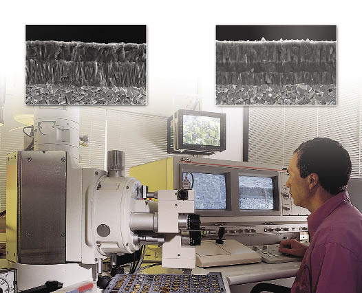
The science of formulating insert substrates and coatings.
Titanium aluminum nitride (TiAlN) and aluminum titanium nitride (AlTiN). Applying a layer of aluminum oxide in combination with these coatings extends tool life in high-heat applications. Aluminum oxide is applied in particular for near-dry and dry machining. AlTiN, which has a higher percentage of aluminum, displays higher surface hardness than TiAlN, which has a higher titanium percentage. AlTiN is commonly used in high-speed machining applications.
Chromium nitride (CrN). With its antiseizure properties, CrN is a preferred solution for combating built-up edge.
Diamond enhances machining performance for nonferrous materials. It is ideal for machining graphite, metal-matrix composites, high-silicon aluminum and other abrasive materials. It is not suitable for effectively machining steels due to chemical reactions that destroy the coating’s bond with the substrate.
In recent years, PVD-coated tools have expanded their market share at the expense of CVD-coated tools. CVD coating thicknesses are typically 5µm to 15µm, while PVD coating thicknesses range from 2µm to 6µm. CVD coatings create undesirable tensile stress when applied to a substrate, while PVD coatings facilitate desired compression stress on the substrate. The thicker CVD coating will usually cause a significant loss of strength at the cutting edge. For that reason, CVD cannot be used on tools that require a very sharp cutting edge.
Assigning new alloying elements to the coating process can improve layer bonding and coating properties. For example, Iscar’s 3P Sumo Tec treatment improves toughness, smoothness and chipping resistance of both PVD and CVD coatings. The Sumo Tec technology also reduces friction and thus energy consumption while increasing resistance to BUE.
The Sumo Tec process acts to reduce microcracks on insert surfaces due to differential contraction as the insert cools after CVD coating. Similarly, the process removes undesirable droplets on the coating surface produced during the PVD coating process. The result is a smoother surface, producing inserts that run cooler, last longer, facilitate better chip flow and can run faster.
Another example is Iscar’s Do-Tec coating technology, which deposits a TiAlN PVD coating on top of a MTCVD Al2O3 coating layer. This combination facilitates medium to high cutting speeds on various grades of cast iron, with high wear and chipping resistance. Cutting speeds from 650 to more than 1,200 sfm can be expected, depending on the type of workpiece material and machining conditions.
Edge Preparation
Edge preparation, or honing, of inserts in many cases is the difference between success and failure in machining. Honing parameters are application specific. High-speed finishing of steel, for example, requires inserts with a different edge preparation than inserts used for roughing. This can be accomplished on almost any type of carbon or alloy steel. Stainless steel and exotic materials are limited. The hones can be as small as 0.0003 " to as large as 0.002 ". This may also include a slight T-land with the hone to reinforce the cutting edge for very harsh applications.
Generally, a substantial hone is required for continuous turning, as well as for milling most steels and cast irons. The amount of the hone would depend on the grade of carbide and type of coating (CVD or PVD). For severe interrupted cuts, a heavy hone or a T-land edge is a prerequisite. Depending on the type of coating, the hone could be close to 0.002 ".
In contrast, small hones (down to 0.0004 ") and sharp edges are required on inserts for machining stainless steels and high-temperature alloys due to their BUE tendency. Specials can be ordered with even smaller hones. The same sharp edges are required for machining aluminum.
For example, Iscar produces a range of inserts with helical cutting edges—the edge profile progresses uniformly around a cylindrical surface in an axial direction. The helical direction resembles a spiral. One of the benefits of the helical design is a smoother cutting action. Rather than cutting with a straight-line edge, the helical cutting edge simulates the action of a spiral flute endmill. Having the cutting edge enter the cut in a “spiraling” action rather than all at once reduces chatter and imparts a smoother finish.
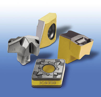
Various coated inserts manufactured using recently developed technology.
In addition, a helical cutting edge enables a heavier cutting load and a higher metal-removal rate while reducing stress. Another advantage of a helical cutting edge is the longer tool life due to reduced tool pressure and heat.
Understanding tool wear and implementing new technology that combats it can improve tool life and machining productivity. In today’s market, in which machine shops are competing not only with the shop across town but ones overseas, it is critical that they take advantage of any competitive edge. CTE
About the Author: Dr. Moshe Goldberg is manager of marketing, training and engineering support for Iscar Ltd., Tefen, Israel. For more information about Iscar, call (877) BY-ISCAR, visit www.iscarmetals.com or enter #320 on the IS form.
Related Glossary Terms
- abrasive
abrasive
Substance used for grinding, honing, lapping, superfinishing and polishing. Examples include garnet, emery, corundum, silicon carbide, cubic boron nitride and diamond in various grit sizes.
- alloys
alloys
Substances having metallic properties and being composed of two or more chemical elements of which at least one is a metal.
- aluminum oxide
aluminum oxide
Aluminum oxide, also known as corundum, is used in grinding wheels. The chemical formula is Al2O3. Aluminum oxide is the base for ceramics, which are used in cutting tools for high-speed machining with light chip removal. Aluminum oxide is widely used as coating material applied to carbide substrates by chemical vapor deposition. Coated carbide inserts with Al2O3 layers withstand high cutting speeds, as well as abrasive and crater wear.
- built-up edge ( BUE)
built-up edge ( BUE)
1. Permanently damaging a metal by heating to cause either incipient melting or intergranular oxidation. 2. In grinding, getting the workpiece hot enough to cause discoloration or to change the microstructure by tempering or hardening.
- built-up edge ( BUE)2
built-up edge ( BUE)
1. Permanently damaging a metal by heating to cause either incipient melting or intergranular oxidation. 2. In grinding, getting the workpiece hot enough to cause discoloration or to change the microstructure by tempering or hardening.
- cast irons
cast irons
Cast ferrous alloys containing carbon in excess of solubility in austenite that exists in the alloy at the eutectic temperature. Cast irons include gray cast iron, white cast iron, malleable cast iron and ductile, or nodular, cast iron. The word “cast” is often left out.
- chatter
chatter
Condition of vibration involving the machine, workpiece and cutting tool. Once this condition arises, it is often self-sustaining until the problem is corrected. Chatter can be identified when lines or grooves appear at regular intervals in the workpiece. These lines or grooves are caused by the teeth of the cutter as they vibrate in and out of the workpiece and their spacing depends on the frequency of vibration.
- chemical vapor deposition ( CVD)
chemical vapor deposition ( CVD)
High-temperature (1,000° C or higher), atmosphere-controlled process in which a chemical reaction is induced for the purpose of depositing a coating 2µm to 12µm thick on a tool’s surface. See coated tools; PVD, physical vapor deposition.
- composites
composites
Materials composed of different elements, with one element normally embedded in another, held together by a compatible binder.
- cutting speed
cutting speed
Tangential velocity on the surface of the tool or workpiece at the cutting interface. The formula for cutting speed (sfm) is tool diameter 5 0.26 5 spindle speed (rpm). The formula for feed per tooth (fpt) is table feed (ipm)/number of flutes/spindle speed (rpm). The formula for spindle speed (rpm) is cutting speed (sfm) 5 3.82/tool diameter. The formula for table feed (ipm) is feed per tooth (ftp) 5 number of tool flutes 5 spindle speed (rpm).
- edge preparation
edge preparation
Conditioning of the cutting edge, such as a honing or chamfering, to make it stronger and less susceptible to chipping. A chamfer is a bevel on the tool’s cutting edge; the angle is measured from the cutting face downward and generally varies from 25° to 45°. Honing is the process of rounding or blunting the cutting edge with abrasives, either manually or mechanically.
- endmill
endmill
Milling cutter held by its shank that cuts on its periphery and, if so configured, on its free end. Takes a variety of shapes (single- and double-end, roughing, ballnose and cup-end) and sizes (stub, medium, long and extra-long). Also comes with differing numbers of flutes.
- feed
feed
Rate of change of position of the tool as a whole, relative to the workpiece while cutting.
- flank wear
flank wear
Reduction in clearance on the tool’s flank caused by contact with the workpiece. Ultimately causes tool failure.
- fracture toughness
fracture toughness
Critical value (KIC) of stress intensity. A material property.
- gang cutting ( milling)
gang cutting ( milling)
Machining with several cutters mounted on a single arbor, generally for simultaneous cutting.
- hardness
hardness
Hardness is a measure of the resistance of a material to surface indentation or abrasion. There is no absolute scale for hardness. In order to express hardness quantitatively, each type of test has its own scale, which defines hardness. Indentation hardness obtained through static methods is measured by Brinell, Rockwell, Vickers and Knoop tests. Hardness without indentation is measured by a dynamic method, known as the Scleroscope test.
- high-speed steels ( HSS)
high-speed steels ( HSS)
Available in two major types: tungsten high-speed steels (designated by letter T having tungsten as the principal alloying element) and molybdenum high-speed steels (designated by letter M having molybdenum as the principal alloying element). The type T high-speed steels containing cobalt have higher wear resistance and greater red (hot) hardness, withstanding cutting temperature up to 1,100º F (590º C). The type T steels are used to fabricate metalcutting tools (milling cutters, drills, reamers and taps), woodworking tools, various types of punches and dies, ball and roller bearings. The type M steels are used for cutting tools and various types of dies.
- lubricity
lubricity
Measure of the relative efficiency with which a cutting fluid or lubricant reduces friction between surfaces.
- metal-removal rate
metal-removal rate
Rate at which metal is removed from an unfinished part, measured in cubic inches or cubic centimeters per minute.
- metalcutting ( material cutting)
metalcutting ( material cutting)
Any machining process used to part metal or other material or give a workpiece a new configuration. Conventionally applies to machining operations in which a cutting tool mechanically removes material in the form of chips; applies to any process in which metal or material is removed to create new shapes. See metalforming.
- metalworking
metalworking
Any manufacturing process in which metal is processed or machined such that the workpiece is given a new shape. Broadly defined, the term includes processes such as design and layout, heat-treating, material handling and inspection.
- milling
milling
Machining operation in which metal or other material is removed by applying power to a rotating cutter. In vertical milling, the cutting tool is mounted vertically on the spindle. In horizontal milling, the cutting tool is mounted horizontally, either directly on the spindle or on an arbor. Horizontal milling is further broken down into conventional milling, where the cutter rotates opposite the direction of feed, or “up” into the workpiece; and climb milling, where the cutter rotates in the direction of feed, or “down” into the workpiece. Milling operations include plane or surface milling, endmilling, facemilling, angle milling, form milling and profiling.
- physical vapor deposition ( PVD)
physical vapor deposition ( PVD)
Tool-coating process performed at low temperature (500° C), compared to chemical vapor deposition (1,000° C). Employs electric field to generate necessary heat for depositing coating on a tool’s surface. See CVD, chemical vapor deposition.
- plastic deformation
plastic deformation
Permanent (inelastic) distortion of metals under applied stresses that strain the material beyond its elastic limit.
- polycrystalline cubic boron nitride ( PCBN)
polycrystalline cubic boron nitride ( PCBN)
Cutting tool material consisting of polycrystalline cubic boron nitride with a metallic or ceramic binder. PCBN is available either as a tip brazed to a carbide insert carrier or as a solid insert. Primarily used for cutting hardened ferrous alloys.
- rake
rake
Angle of inclination between the face of the cutting tool and the workpiece. If the face of the tool lies in a plane through the axis of the workpiece, the tool is said to have a neutral, or zero, rake. If the inclination of the tool face makes the cutting edge more acute than when the rake angle is zero, the rake is positive. If the inclination of the tool face makes the cutting edge less acute or more blunt than when the rake angle is zero, the rake is negative.
- stainless steels
stainless steels
Stainless steels possess high strength, heat resistance, excellent workability and erosion resistance. Four general classes have been developed to cover a range of mechanical and physical properties for particular applications. The four classes are: the austenitic types of the chromium-nickel-manganese 200 series and the chromium-nickel 300 series; the martensitic types of the chromium, hardenable 400 series; the chromium, nonhardenable 400-series ferritic types; and the precipitation-hardening type of chromium-nickel alloys with additional elements that are hardenable by solution treating and aging.
- titanium aluminum nitride ( TiAlN)
titanium aluminum nitride ( TiAlN)
Often used as a tool coating. AlTiN indicates the aluminum content is greater than the titanium. See coated tools.
- titanium aluminum nitride ( TiAlN)2
titanium aluminum nitride ( TiAlN)
Often used as a tool coating. AlTiN indicates the aluminum content is greater than the titanium. See coated tools.
- titanium carbonitride ( TiCN)
titanium carbonitride ( TiCN)
Often used as a tool coating. See coated tools.
- titanium nitride ( TiN)
titanium nitride ( TiN)
Added to titanium-carbide tooling to permit machining of hard metals at high speeds. Also used as a tool coating. See coated tools.
- turning
turning
Workpiece is held in a chuck, mounted on a face plate or secured between centers and rotated while a cutting tool, normally a single-point tool, is fed into it along its periphery or across its end or face. Takes the form of straight turning (cutting along the periphery of the workpiece); taper turning (creating a taper); step turning (turning different-size diameters on the same work); chamfering (beveling an edge or shoulder); facing (cutting on an end); turning threads (usually external but can be internal); roughing (high-volume metal removal); and finishing (final light cuts). Performed on lathes, turning centers, chucking machines, automatic screw machines and similar machines.
- wear resistance
wear resistance
Ability of the tool to withstand stresses that cause it to wear during cutting; an attribute linked to alloy composition, base material, thermal conditions, type of tooling and operation and other variables.
Author
News items authored by Cutting Tool Engineering have been written or edited by the editors of Cutting Tool Engineering magazine. The reports represent material submitted to CTE by outside authors, and edited by CTE editors for style and accuracy.