The combination of a loading robot and a CNC tool-and-cutter grinding machine allows unattended resharpening of endmills.
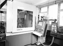
Figure 1: CNC tool-and-cutter grinding machine with loading robot.
Tool-resharpening shops not only have to produce CNC-quality tools that perform as well or better than new tools. They also must offer their customers the shortest possible turnaround time at competitive prices. To optimize the use of a CNC grinding machine, these shops must consider incorporating automatic tool loading and resharpening to complete jobs unattended during night shifts and weekends.
For tool-grinding shops, the greatest obstacle to unattended machining is the need to change parameters from tool to tool. These shops typically receive a wide variety of tools from a broad base of customers. Endmills make up a large percentage of the tools sent for reconditioning. Endmills come in a wide range of geometries, including number of flutes, left- or right-hand spirals, and hook and clearance angles, and are made from various materials, such as carbide, HSS, and cermet. They also have varying amounts of wear and nicks on their cutting edges.
Some customers may want their endmills reground completely (flute, diameter, and end). Others may request that only certain parameters be reconditioned (diameter configurations and chamfers). Consequently, the grinder never resharpens tools from different customers in the same way. With customers requiring short turnaround times, there is never enough time to wait for more of a customer’s endmills to come in so that tools requiring similar work might be batched together. Therefore, each batch consists of tools from a variety of customers. Resharpening these endmills manually can be extremely time-consuming and labor-intensive. For a shop to grind tools profitably, it must automate the process.
A shop looking to upgrade its machinery and improve its productivity may consider investing in a 5-axis tool-and-cutter grinding machine with a 3-axis automatic tool loader and intelligent software (Figure 1). The faster turnaround and lower labor costs provided by unattended tool resharpening are fundamental to the justification of this kind of investment. A machine capable of unattended resharpening should be equipped with a stationary dividing head and a double-end spindle to accept a maximum of six different grinding wheels. As shown in Figure 2, this kinematic design concept allows for the accurate loading of endmills and the installation of an automatic dressing device, tailstock, steady rest, or other special tooling on the double T-slotted table.
With a CNC that incorporates digital AC drives and an integrated PC, the grinder can offer different options for sending or receiving data. The operator can communicate with the machine through a modem, printer port, or network. Programming software can be fine-tuned to meet the specific requirements of CNC tool resharpening.
Programming and Preparation
Figure 2: Kinematic concept of a 5-axis tool-and-cutter grinding machine.
As operators load a pallet with endmills that are to be reground during an unattended shift, they must select tools with some features in common. The endmills have to be sorted and grouped by their shaft diameters, since the installed collet or toolholder in which they are directly loaded only allows a certain diameter tolerance. Ideally, there should be enough endmills of the same material to fill a pallet, since only one pallet of tools can be reground during an unattended shift. (Some pallets can hold approximately 240 endmills, depending on the tool diameter.) To resharpen endmills of the same material, the two spindle ends do not have to be fitted with two wheels of different materials, each demanding its own schedule of maintenance and dressing.
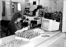
Figure 3: Input of tool features on the grinding machine’s PC for unattended resharpening.
The operator can enter data for a specific tool on the machine’s PC or offline on a separate workstation (Figure 3). Spreadsheet programs offer the necessary format for entering all pertinent data about an individual tool in a specific location on the pallet. The use of databases of industry-standard tool features minimizes the data that must be entered for each customer’s endmills. Such databases can include standard values for hook angles, flute depths, and clearance angles. The operator saves time by calling up standard tool features from these databases before the tool program is generated.
For each tool, the operator must enter the pallet ID number, row, column, tool type, special tool features (i.e. corner radius), number of teeth, end configuration, tool diameter and length, grinding length, and the amount of stock to be removed from the diameter and end of the specific tool. The selected grinding operation (i.e. fluting, gashing, end grinding, or OD grinding) can be activated when the corresponding tool features in the spreadsheet file are loaded into the PC.
A 3-D electronic probing system is used to determine the location of features on each tool once it is loaded into the grinder. Because it is too time-consuming for the probe to measure tool features such as hook angle and cutting length, the operator enters these measurements in the spreadsheet file to decide what features will be ground on each endmill.
It takes about an hour to complete programming for 80 endmills of different styles. This preparation can be done offline during the day shift while the machines are used for resharpening or manufacturing. The collected data can be uploaded to the PC at any time during the day shift with the help of the integrated RS-232 port. Once the data are uploaded, the operator can set up the grinding machine for unattended operation.
Setup Sequence
Because different toolholders may be used for attended machining during the day shift, the operator may have to change the toolholder to a collet that fits the shanks of the tools for unattended resharpening during the night and weekend shifts. Setting up the pallet is accomplished in three steps.
1) The only tool feature that restricts the use of automatic loading is the end configuration. For example, center-cutting endmills may have two or three flutes and one center-cutting wing. These individual endmills are aligned in the pallet by their center-cutting wings so that the probe can determine the center-cutting edge on each tool. Endmills without center-cutting wings, such as 4-flute roughing endmills, do not have to be aligned; the probe simply finds the location of one of the flutes. The pallet with tools is manually loaded and positioned. Then the operator secures it in the shuttle, which takes the pallet into the robot loader.
2) During the orientation of the loader to the pallet, the loader reads the code number of the individual pallet and calls up data about this specific pallet from memory. These data include the pallet’s starting point in the x-, y-, and z-axes and the spacing between the rows and columns.
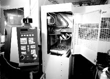
Figure 4: Detailed view of the loader.
3) Finally, the machine checks to ensure that the two grippers on the loader are for the correct tool diameters. The operator now sets the grinder for automatic operation by entering the name of the spreadsheet file for the pallet of endmills to be reground. Initializing the operation, the machine checks and compares the pallet code entered in the spreadsheet file with the actual pallet code.
The first endmill is gripped and automatically loaded in the grinding-machine collet (Figure 4). As soon as the loader arm retracts through the loading door, the probing program is executed. The loader immediately grips the next endmill and moves into ready position. If necessary, the probe will check the tool length, the tool diameter, and the position of the center-cutting wing to determine the tool’s precise location in the grinder. As soon as the probe establishes the tool’s location, the tool features are downloaded from the selected database. After all the tool features are known, the grinding software calculates and compiles an ISO-code program in a matter of seconds. This tool program is transferred to the CNC and executed. The resharpening of the endmill starts immediately.
After the last operation, the loader arm moves into the loading position and grips the ground endmill with one gripper. Then the arm retracts and turns to allow the other gripper to load the next unground endmill into the collet. This sequence of operations is repeated until all endmills have been resharpened. After completion of the process, the software can turn off the machine and the loading robot.
Process Control
Numerous safety functions guarantee the success of the unattended tool-resharpening process. The loader will recognize tools that are poorly gripped in the jaws, and the probe will detect tools that are improperly clamped in the collet. For these or other substantial problems, such as a wheel crash, lack of coolant supply, or hydraulic failure, the machine will interrupt its operation. For small problems such as misguided coolant or dirt in the collet, the loader will unload the tool in question and move on to the next tool. After a number of small errors, the machine will interrupt its operation.
Besides the standard safety control of a CNC tool-and-cutter grinding machine, the loading robot is also subject to safety checks by the machine control. In case of problems, the internal modem can call a public telephone number automatically to alarm an operator at home.
To improve the process control, the individual wheel programs can accept parameters to automatically compensate for wheel wear. In addition, the helix angle on each endmill can be checked individually to ensure that the tools are reconditioned to the customer’s specifications regardless of wear and previously unqualified resharpening.
After completion of all endmills, the operator has access to a protocol file where the control stores data for each ground tool. Such data can be reviewed later for quality control and SPC. Some endmills may not have been ground due to faulty data; the operator may have entered the wrong tool diameter, for example. The pallet locations of these unground endmills are marked off in the protocol file so that the tools can be removed.
Utilization Cycle
A CNC tool-and-cutter grinding machine equipped with a loading robot can significantly increase the productivity of a tool-resharpening shop during the day shift as well as during the night and weekend shifts. During the day shift, the machine can be used for grinding profile tools, high-performance drills, or other tools that require special file formats or different wheel setups. The individual tools are mounted in toolholders and measured in a tool presetter. At the same time, the desired stock-removal data is transferred from the PC presetter to the control. At the end of the grinding cycle of the previously ground tool, the data transfer is initiated and the next tool program is automatically calculated and compiled. During this process, the next tool can be installed in the machine, including the toolholder if necessary, and the machine can be started again. The idle time of the machine is significantly reduced to the time it takes to change the tool (in most cases, no more than a few seconds).
With consistent tool quality and simple programming, the unattended operation during the night and weekend shifts guarantees fast return on investment and reduced labor costs. The prolonged uptime of the machine lowers the hourly rate of the equipment. It also eliminates the need for additional labor and additional shifts.
The integration of a network will simplify the control of the unattended tool-resharpening process so that the status of the individual machines can be supervised at any time. This will be even more significant in the future with the combination of loading robots and new, smaller CNC tool-and-cutter grinding machines. With the identical kinematics, control, and software, these smaller machines will guarantee the same reliable operation.
About the Authors
Werner Morach is managing director of E. Weber AG, Langnau, Switzerland. Peter Beyeler is sales manager and Hartmut Rühl is manager of software R&D at J. Schneeberger Maschinen AG, Roggwil, Switzerland.
Related Glossary Terms
- 3-D
3-D
Way of displaying real-world objects in a natural way by showing depth, height and width. This system uses the X, Y and Z axes.
- clearance
clearance
Space provided behind a tool’s land or relief to prevent rubbing and subsequent premature deterioration of the tool. See land; relief.
- collet
collet
Flexible-sided device that secures a tool or workpiece. Similar in function to a chuck, but can accommodate only a narrow size range. Typically provides greater gripping force and precision than a chuck. See chuck.
- computer numerical control ( CNC)
computer numerical control ( CNC)
Microprocessor-based controller dedicated to a machine tool that permits the creation or modification of parts. Programmed numerical control activates the machine’s servos and spindle drives and controls the various machining operations. See DNC, direct numerical control; NC, numerical control.
- coolant
coolant
Fluid that reduces temperature buildup at the tool/workpiece interface during machining. Normally takes the form of a liquid such as soluble or chemical mixtures (semisynthetic, synthetic) but can be pressurized air or other gas. Because of water’s ability to absorb great quantities of heat, it is widely used as a coolant and vehicle for various cutting compounds, with the water-to-compound ratio varying with the machining task. See cutting fluid; semisynthetic cutting fluid; soluble-oil cutting fluid; synthetic cutting fluid.
- dividing head
dividing head
Attaches to a milling-machine table and precisely indexes the workpiece. Allows equally spaced cuts to be made when machining gear and sprocket teeth, spline keys, serrations, etc.
- dressing
dressing
Removal of undesirable materials from “loaded” grinding wheels using a single- or multi-point diamond or other tool. The process also exposes unused, sharp abrasive points. See loading; truing.
- endmill
endmill
Milling cutter held by its shank that cuts on its periphery and, if so configured, on its free end. Takes a variety of shapes (single- and double-end, roughing, ballnose and cup-end) and sizes (stub, medium, long and extra-long). Also comes with differing numbers of flutes.
- flutes
flutes
Grooves and spaces in the body of a tool that permit chip removal from, and cutting-fluid application to, the point of cut.
- fluting
fluting
Cutting straight or spiral grooves in drills, endmills, reamers and taps to improve cutting action and remove chips.
- grinding
grinding
Machining operation in which material is removed from the workpiece by a powered abrasive wheel, stone, belt, paste, sheet, compound, slurry, etc. Takes various forms: surface grinding (creates flat and/or squared surfaces); cylindrical grinding (for external cylindrical and tapered shapes, fillets, undercuts, etc.); centerless grinding; chamfering; thread and form grinding; tool and cutter grinding; offhand grinding; lapping and polishing (grinding with extremely fine grits to create ultrasmooth surfaces); honing; and disc grinding.
- grinding machine
grinding machine
Powers a grinding wheel or other abrasive tool for the purpose of removing metal and finishing workpieces to close tolerances. Provides smooth, square, parallel and accurate workpiece surfaces. When ultrasmooth surfaces and finishes on the order of microns are required, lapping and honing machines (precision grinders that run abrasives with extremely fine, uniform grits) are used. In its “finishing” role, the grinder is perhaps the most widely used machine tool. Various styles are available: bench and pedestal grinders for sharpening lathe bits and drills; surface grinders for producing square, parallel, smooth and accurate parts; cylindrical and centerless grinders; center-hole grinders; form grinders; facemill and endmill grinders; gear-cutting grinders; jig grinders; abrasive belt (backstand, swing-frame, belt-roll) grinders; tool and cutter grinders for sharpening and resharpening cutting tools; carbide grinders; hand-held die grinders; and abrasive cutoff saws.
- helix angle
helix angle
Angle that the tool’s leading edge makes with the plane of its centerline.
- high-speed steels ( HSS)
high-speed steels ( HSS)
Available in two major types: tungsten high-speed steels (designated by letter T having tungsten as the principal alloying element) and molybdenum high-speed steels (designated by letter M having molybdenum as the principal alloying element). The type T high-speed steels containing cobalt have higher wear resistance and greater red (hot) hardness, withstanding cutting temperature up to 1,100º F (590º C). The type T steels are used to fabricate metalcutting tools (milling cutters, drills, reamers and taps), woodworking tools, various types of punches and dies, ball and roller bearings. The type M steels are used for cutting tools and various types of dies.
- inner diameter ( ID)
inner diameter ( ID)
Dimension that defines the inside diameter of a cavity or hole. See OD, outer diameter.
- outer diameter ( OD)
outer diameter ( OD)
Dimension that defines the exterior diameter of a cylindrical or round part. See ID, inner diameter.
- process control
process control
Method of monitoring a process. Relates to electronic hardware and instrumentation used in automated process control. See in-process gaging, inspection; SPC, statistical process control.
- quality assurance ( quality control)
quality assurance ( quality control)
Terms denoting a formal program for monitoring product quality. The denotations are the same, but QC typically connotes a more traditional postmachining inspection system, while QA implies a more comprehensive approach, with emphasis on “total quality,” broad quality principles, statistical process control and other statistical methods.
- statistical process control ( SPC)
statistical process control ( SPC)
Statistical techniques to measure and analyze the extent to which a process deviates from a set standard.
- steady rest
steady rest
Supports long, thin or flexible work being turned on a lathe. Mounts on the bed’s ways and, unlike a follower rest, remains at the point where mounted. See follower rest.
- tolerance
tolerance
Minimum and maximum amount a workpiece dimension is allowed to vary from a set standard and still be acceptable.
- toolholder
toolholder
Secures a cutting tool during a machining operation. Basic types include block, cartridge, chuck, collet, fixed, modular, quick-change and rotating.