Kyocera Corp. brings a surface-hardening hybrid structure to a cermet substrate by combining conventional cermet and a metal-bonded phase with a high melting point. This reduces the likelihood of chips adhering to an insert during machining and provides a stable, machined surface to extend tool life and improve surface finishes, according to the Japanese toolmaker.
The new TN620- and PV720-grade inserts have a tough cermet with enhanced resistance to chipping and thermal shock for the internal structure and a cermet with a hardness from about 1,800 to 1,900 HV for the surface structure, noted Eric Jenkins, senior applications engineer for Kyocera Precision Tools Inc. By enhancing hardness and toughness, the hybrid cermet inserts reportedly improve abrasion and fracture resistance by 50 percent compared to the company’s conventional cermet inserts.
Courtesy of Kyocera
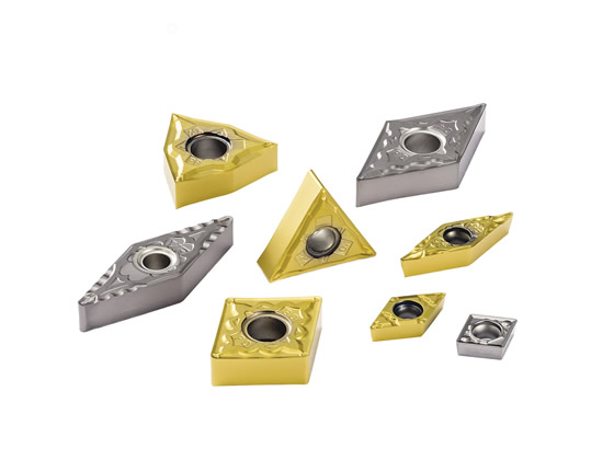
Kyocera reports that its TN620 (silver) and PV720 (gold) hybrid cermet inserts provide a 50 percent improvement in abrasion and fracture resistance compared to the company’s conventional cermet grades.

Courtesy of Kyocera
The metal-bonded phase in hybrid cermet inserts from Kyocera is shown in green.
In addition, the new cermet materials improve flexural strength by incorporating a “hybrid hard phase” comprised of particles from 0.5µm to 2.0µm, Jenkins explained.
While TN620 inserts are uncoated, PV720 inserts are PVD-coated with Kyocera’s Megacoat Nano multilayer coating, which the company reports is its first cermet grade to incorporate that technology. Jenkins added that the coating is applied to the company’s PR15-series milling inserts and PR1425-grade inserts for turning small parts.
Targeted for carbon and alloy steel applications, Kyocera recommends a cutting speed from 100 to 300 m/min. (330 to 1,000 sfm) for the TN620 inserts and 100 to 350 m/min. (330 to 1,150 sfm) for the PV720.
For more information about Kyocera Precision Tools Inc., Hendersonville, N.C., call (800) 823-7284 or visit www.kyoceraprecisiontools.com.
 |
About the Author |
Contact Details
Related Glossary Terms
- Vickers hardness number ( HV)
Vickers hardness number ( HV)
Number related to the applied load and surface area of the permanent impression made by a square-based pyramidal diamond indenter having included face angles of 136º. The Vickers hardness number is a ratio of the applied load in kgf, multiplied by 1.8544, and divided by the length of diagonal squared.
- cutting speed
cutting speed
Tangential velocity on the surface of the tool or workpiece at the cutting interface. The formula for cutting speed (sfm) is tool diameter 5 0.26 5 spindle speed (rpm). The formula for feed per tooth (fpt) is table feed (ipm)/number of flutes/spindle speed (rpm). The formula for spindle speed (rpm) is cutting speed (sfm) 5 3.82/tool diameter. The formula for table feed (ipm) is feed per tooth (ftp) 5 number of tool flutes 5 spindle speed (rpm).
- gang cutting ( milling)
gang cutting ( milling)
Machining with several cutters mounted on a single arbor, generally for simultaneous cutting.
- hardness
hardness
Hardness is a measure of the resistance of a material to surface indentation or abrasion. There is no absolute scale for hardness. In order to express hardness quantitatively, each type of test has its own scale, which defines hardness. Indentation hardness obtained through static methods is measured by Brinell, Rockwell, Vickers and Knoop tests. Hardness without indentation is measured by a dynamic method, known as the Scleroscope test.
- milling
milling
Machining operation in which metal or other material is removed by applying power to a rotating cutter. In vertical milling, the cutting tool is mounted vertically on the spindle. In horizontal milling, the cutting tool is mounted horizontally, either directly on the spindle or on an arbor. Horizontal milling is further broken down into conventional milling, where the cutter rotates opposite the direction of feed, or “up” into the workpiece; and climb milling, where the cutter rotates in the direction of feed, or “down” into the workpiece. Milling operations include plane or surface milling, endmilling, facemilling, angle milling, form milling and profiling.
- turning
turning
Workpiece is held in a chuck, mounted on a face plate or secured between centers and rotated while a cutting tool, normally a single-point tool, is fed into it along its periphery or across its end or face. Takes the form of straight turning (cutting along the periphery of the workpiece); taper turning (creating a taper); step turning (turning different-size diameters on the same work); chamfering (beveling an edge or shoulder); facing (cutting on an end); turning threads (usually external but can be internal); roughing (high-volume metal removal); and finishing (final light cuts). Performed on lathes, turning centers, chucking machines, automatic screw machines and similar machines.
Author

Alan holds a bachelor’s degree in journalism from Southern Illinois University Carbondale. Including his 20 years at CTE, Alan has more than 30 years of trade journalism experience.