Tool balancing basics

Author Yesenia Duran
Published
October 21, 2020 - 08:30am

Unbalanced tools are a problem. They generate vibration, which may lead to broken tools, shorter spindle life and higher workpiece roughness.

Implementing balancing protocols for a machining process helps protect a machine tool. Balanced tools reduce vibrations and are needed whether cutting at 44,000 or 3,000 rpm.

Like many things, tool balancing merits a cost-benefit analysis. While new technology might affect the way balancing is performed and justified, the need for analysis is unchanged.

Cause of Imbalance

Tool imbalance is caused when the center of gravity of a rotating mass is not aligned with its rotating axis.

“So the unbalance is a distance that creates an eccentricity,” said Manager Francesco D’Alessandro of Balance Systems Corp. in Wixom, Michigan. “This eccentricity creates vibration.”


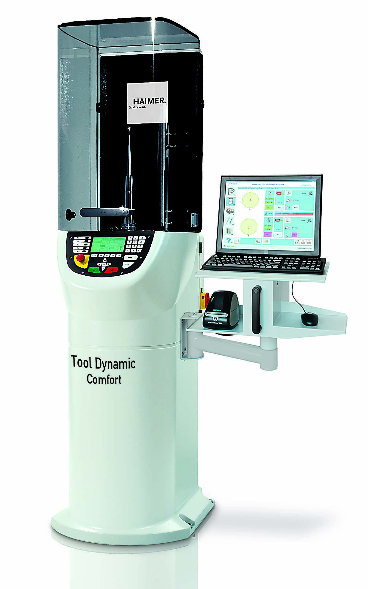
The Tool Dynamic TD Comfort balancing machine (above) is equipped with a PC, keyboard, mouse and monitor. Image courtesy of Haimer USA

Defined as the distance from the center of rotation of a tool to its true center of mass, eccentricity measures the extent to which tool weight is off-center. If eccentricity is measured in microns and tool mass is measured in kilograms, these units yield imbalance in gram millimeters, a common unit.

President Thomas Hoenig of GTI Spindle Technology Inc. in Manchester, New Hampshire, agrees that tool balancing is extremely important. Imbalance damages spindle bearings and other spindle components. Imbalance also causes chatter on machined and ground parts. And unbalanced tools cause premature tooling wear through taper damage to the tooling interface.

“Tooling balance should be done almost always,” he said. “The only time it does not apply is on very slow rpm machining operations, such as tapping holes, or some slow lathe cuts. Any machining operation over 3,000 rpm, balance is critical.”

However, President Brendt Holden of Haimer USA LLC in Villa Park, Illinois, said in many cases, some of the most dramatic advantages of balancing tooling assemblies can be found at low rpm for things like boring heads or facemill arbor assemblies.

“Our advice is to always look at applications that present challenges that no one can figure out how to solve,” he said. “Maybe they looked at the fixturing or the machine condition or the cutting tools, but still they are not getting the performance they wanted. Did they look at balancing? If not, this would be the time to investigate balancing.”

Holden said people today want to reduce cycle time, which may mean decreasing the number of tool changes. If a shop formerly used roughing, semifinishing and finishing tools to complete a part but now prefers to use only one tool for the job, that can cause issues with balance. Also, a special tool might be designed to drill, counterbore and chamfer. With pockets in different positions, more attention must be paid to balancing to achieve quality specifications.

Necessary Balancing

“Theoretically speaking, balancing is always necessary,” D’Alessandro said. “Although in case of very low spindle rpm (less than 3,000 rpm) and poor workpiece finishing goals, tool balancing might be skipped.”

That said, modern machine tools tend to have high spindle speeds to achieve greater cutting volumes or reach high cutting speed requirements — for example, when machining Inconel.

“The increases of these values have also raised the demands for better tools and holders, which then require to balance the tool more frequently than before and at a lower residual imbalance,” D’Alessandro said. “In order to monitor this phenomenon, it may be helpful installing on the machine a permanent spindle monitoring system, such as the B-Safe sensor, which is able to give visual aids and alerts to the operator when the vibration is too high.”


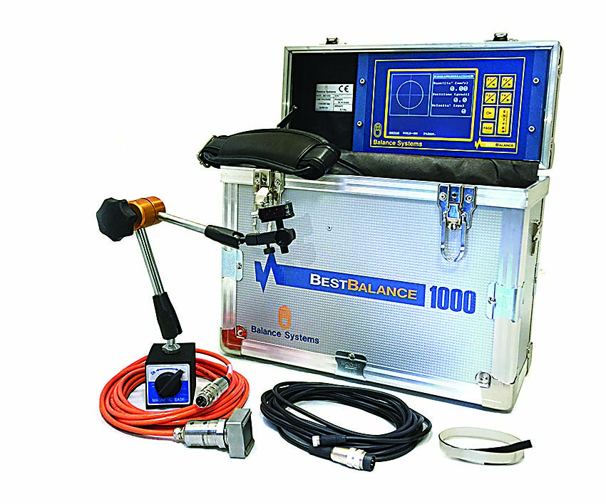
The Best Balance 1000 is a portable device for measuring and correcting vibrations of rotating components due to imbalance. Image courtesy of Balance Systems

Sources said companies gain 15% to 25% in productivity and tool life on average when they begin balancing tooling assemblies, with even better gains if they started with poor balance situations. Although balancing will not solve every problem with a cutting process, estimates are that balancing can solve at least a third of machining issues, especially ones that never seem to go away.

D’Alessandro said the most common problems that end users experience before calling Balance Systems are tool breakage and workpiece chatter. Analysis often reveals that these difficulties are due to vibration, which is generated mainly by tool imbalance.

“The imbalance is sneaky because it cannot be seen and can be felt only when it is too late,” he said. “For this reason, I like to call it the silent killer of machine tools.”

Holden said his most frequent questions from customers are not about balancing — at least at first.

“However, during our discussions the topic of balancing comes up as a clear need as it relates to solving their problems,” he said. “For example, our customer might call about surface finish or tool life issues. Then upon examination, we determine that they have a runout problem. While that runout might not be visible via static checking on a tool presetter or during a slow manual rotation in the machine spindle, once the tool is spinning dynamically at the machine-set rpm, the runout increases if the toolholder assembly is unbalanced. Then we run a test to balance the assembly and find that once balanced, the runout goes away and the customer is happy.”

Holden said customers also complain that they are not able to run at desired speeds and feeds when machining a part.

“Diving into things, we realize that some of the toolholder assemblies used in the production process had unbalance,” he said. “Then they balance the assemblies, and the customers are then able to machine their parts at the appropriate feeds and speeds as they had originally planned.”

Hoenig said spindle installation issues, such as balance, misalignment and encoder faults, are what he hears about most from customers.

“When a spindle is sent for repair by the customer,” he said, “many times they are sent without all the rotating components.”

Pulleys, rotary unions, hubs, drawbars and other items are left behind for various reasons. When those components then are mounted on a newly rebuilt/balanced spindle, it can be thrown out of balance and alignment.

“So it’s very important that all the parts be sent together to be balanced together,” Hoenig said.

Most service technicians and end users unfortunately do not have the balancing equipment to perform necessary corrections in the field. GTI Spindle Technology typically has to perform a service call when that happens.


The BVK3-10 is a general-purpose vertical balancing machine for disc-shaped parts.  Image courtesy of Balance Systems

How to Balance

The balancing process of a tool is pretty straightforward. Almost every tool on the market has a balancing grade indicated with a G followed by a number, according to ISO standards. This is a reference declared by a tool manufacturer. If a user types the information into the software of a balancer, along with the tool assembly weight and rpm, he or she gets the target residual imbalance that should be achieved during balancing. The machine then indicates the mechanical corrections based on the selected tool dimensions and balancing mode: A) by “sliding weights,” B) by “adding screws,” C) by rotating “eccentric rings” or D) by “free balancing.”

When milling, if vibration is too high, the No. 1 problem with a workpiece is chatter.

Hoenig said precautions should be taken with particular metals when balancing. Some carbide tools need special grinding wheels to remove weight for balancing. Weight removal always is recommended for high-speed tools because extra weight could fly off and cause damage or injury.

He said the best way to figure out how to balance a tool is with a vibration analyzer/balancer. GTI Spindle Technology produces a wireless version that runs on Apple’s iPad.

Holden said a shop needs an in-house balancing machine to check the condition of tooling assemblies.

“Even if you order special form tools to come to you balanced, how do you know if it really arrives to your facility balanced?” he said. “We have some larger customers that simply use the balancing machine as a go/no gauge in order to confirm that their assemblies are balanced every time.”

Holden said a balancing machine tells how to remove or displace weight from or add weight to a tooling assembly to balance it. To determine balancing, it is important to look at the makeup of a tooling assembly. Can material be removed from all areas of the holder without damaging it? For example, would material be removed from coolant ports or hydraulic chambers? Or if weight will be displaced via balancing rings, will there be interference with the workpiece?

“All of these things need to be considered,” he said. “But in almost all cases, there is a good method to bring a tool within balancing utilizing one of these methods (removing, adding or displacing weight).”

Haimer USA’s most popular balancing machine is the Tool Dynamic TD Comfort, which Holden recommends based on its ease of use and accuracy.

“We use a spindle that clamps the tooling assembly as if held in the machine tool spindle, and the machine itself has a hard-bearing spindle that uses centrifugal force sensors to measure the unbalance of the tooling assembly,” he said. “The ease of use comes from the software that guides the user through an easy modification process.”

Balance Systems’ offerings are for machine shops, machine tool field maintenance and tool and holder manufacturing.

“For end users of machine tools,” D’Alessandro said, “at present the most popular machine for this application is our BVK3-10.”

He explained that an operator places a tool in the BVK3-10, loads the related part program and closes the guard. The machine starts measuring the initial imbalance and then tells the operator the correction to apply to the part.

For field maintenance, D’Aless-andro recommends portable balancing equipment, such as the Best Balance 1000. The main benefit of this model is that a user does not need to remove a tool from a spindle and put the tool on the balancer. The balancing process can be performed directly on a machine tool. The same equipment also may be used to balance other types of spindles, including those on grinding machines.

“For manufacturers of tools and toolholders, we also developed a specific automatic balancing machine: the BVK4,” he said. “We have vast experience in machine automation and can balance these parts automatically. This model has a proprietary touch detection system that removes the material — i.e., balances — very precisely. BVK4 is used in mid/high-volume production contexts.”

GTI Spindle Technology’s BalancePro for Field Balancing is an iPad/iOS app for balancing one- and two-plane rotating machinery. By connecting to GTI Spindle Technology’s acceleration measurement system and tachometer, the app utilizes vibration amplitude and phase signal to automatically calculate corrective balancing weights and their angular positions. Balance jobs may be stored and loaded for later use.

Tool balancing may not always be necessary but is generally a good idea.

“To make it easy to understand,” Holden said, “would you ever consider that there is a time that it is fine to drive your car with unbalanced wheels? Probably not.”   


Related Glossary Terms

  • arbor

    arbor

    Shaft used for rotary support in machining applications. In grinding, the spindle for mounting the wheel; in milling and other cutting operations, the shaft for mounting the cutter.

  • boring

    boring

    Enlarging a hole that already has been drilled or cored. Generally, it is an operation of truing the previously drilled hole with a single-point, lathe-type tool. Boring is essentially internal turning, in that usually a single-point cutting tool forms the internal shape. Some tools are available with two cutting edges to balance cutting forces.

  • chatter

    chatter

    Condition of vibration involving the machine, workpiece and cutting tool. Once this condition arises, it is often self-sustaining until the problem is corrected. Chatter can be identified when lines or grooves appear at regular intervals in the workpiece. These lines or grooves are caused by the teeth of the cutter as they vibrate in and out of the workpiece and their spacing depends on the frequency of vibration.

  • coolant

    coolant

    Fluid that reduces temperature buildup at the tool/workpiece interface during machining. Normally takes the form of a liquid such as soluble or chemical mixtures (semisynthetic, synthetic) but can be pressurized air or other gas. Because of water’s ability to absorb great quantities of heat, it is widely used as a coolant and vehicle for various cutting compounds, with the water-to-compound ratio varying with the machining task. See cutting fluid; semisynthetic cutting fluid; soluble-oil cutting fluid; synthetic cutting fluid.

  • counterbore

    counterbore

    Tool, guided by a pilot, that expands a hole to a certain depth.

  • cutting speed

    cutting speed

    Tangential velocity on the surface of the tool or workpiece at the cutting interface. The formula for cutting speed (sfm) is tool diameter 5 0.26 5 spindle speed (rpm). The formula for feed per tooth (fpt) is table feed (ipm)/number of flutes/spindle speed (rpm). The formula for spindle speed (rpm) is cutting speed (sfm) 5 3.82/tool diameter. The formula for table feed (ipm) is feed per tooth (ftp) 5 number of tool flutes 5 spindle speed (rpm).

  • facemill

    facemill

    Milling cutter for cutting flat surfaces.

  • gang cutting ( milling)

    gang cutting ( milling)

    Machining with several cutters mounted on a single arbor, generally for simultaneous cutting.

  • grinding

    grinding

    Machining operation in which material is removed from the workpiece by a powered abrasive wheel, stone, belt, paste, sheet, compound, slurry, etc. Takes various forms: surface grinding (creates flat and/or squared surfaces); cylindrical grinding (for external cylindrical and tapered shapes, fillets, undercuts, etc.); centerless grinding; chamfering; thread and form grinding; tool and cutter grinding; offhand grinding; lapping and polishing (grinding with extremely fine grits to create ultrasmooth surfaces); honing; and disc grinding.

  • lathe

    lathe

    Turning machine capable of sawing, milling, grinding, gear-cutting, drilling, reaming, boring, threading, facing, chamfering, grooving, knurling, spinning, parting, necking, taper-cutting, and cam- and eccentric-cutting, as well as step- and straight-turning. Comes in a variety of forms, ranging from manual to semiautomatic to fully automatic, with major types being engine lathes, turning and contouring lathes, turret lathes and numerical-control lathes. The engine lathe consists of a headstock and spindle, tailstock, bed, carriage (complete with apron) and cross slides. Features include gear- (speed) and feed-selector levers, toolpost, compound rest, lead screw and reversing lead screw, threading dial and rapid-traverse lever. Special lathe types include through-the-spindle, camshaft and crankshaft, brake drum and rotor, spinning and gun-barrel machines. Toolroom and bench lathes are used for precision work; the former for tool-and-die work and similar tasks, the latter for small workpieces (instruments, watches), normally without a power feed. Models are typically designated according to their “swing,” or the largest-diameter workpiece that can be rotated; bed length, or the distance between centers; and horsepower generated. See turning machine.

  • milling

    milling

    Machining operation in which metal or other material is removed by applying power to a rotating cutter. In vertical milling, the cutting tool is mounted vertically on the spindle. In horizontal milling, the cutting tool is mounted horizontally, either directly on the spindle or on an arbor. Horizontal milling is further broken down into conventional milling, where the cutter rotates opposite the direction of feed, or “up” into the workpiece; and climb milling, where the cutter rotates in the direction of feed, or “down” into the workpiece. Milling operations include plane or surface milling, endmilling, facemilling, angle milling, form milling and profiling.

  • tapping

    tapping

    Machining operation in which a tap, with teeth on its periphery, cuts internal threads in a predrilled hole having a smaller diameter than the tap diameter. Threads are formed by a combined rotary and axial-relative motion between tap and workpiece. See tap.

  • toolholder

    toolholder

    Secures a cutting tool during a machining operation. Basic types include block, cartridge, chuck, collet, fixed, modular, quick-change and rotating.

Author

Yesenia Duran is a Chicago-based freelance journalist who covers cutting tools and technology. She can be reached at sennyx@gmail.com.


Contributors

Balance Systems Corp.
248-308-3636
www.balancesystems.com

GTI Spindle Technology Inc.
888-473-9675
www.gtispindle.com

Haimer USA LLC
630-833-1500
www.haimer-usa.com