When it comes to tapping — the process of cutting a thread inside a hole — there’s much to be said for choosing a synchronous approach, as well as tapping hardware tailored to the special characteristics and challenges of that technique.
Synchronous tapping features a rigid tapholder rather than one that’s flexible, or floating. The floating type also is known as a tension-compression tapholder because it allows axial extension and compression to compensate for some mismatch between the machine’s spindle speed and the infeed of the tap. The idea is to prevent damage to the tap and workpiece caused by pushing or pulling during the tapping process.
In rigid tapping, however, spindle rotation and feed rate are synchronized, and the tap can be held rigidly in a chuck. Today, most CNC machines come with synchronized or rigid tap cycles that are easy to program and capable of very accurate tapping depth control, said Mark Johnson, president of Tapmatic Corp. in Post Falls, Idaho.
Other rigid tapping advantages are the result of reduced runout compared with floating tapping.

Synchro Taps reportedly run much faster than conventional taps. Image courtesy of YG-1 Tool (USA)
When rigid tapping, “you are not allowing the tool to follow whatever path it wants to follow,” said Mark Ford, director of global product management for threading tools at YG-1 Tool (USA) Co. in Vernon Hills, Illinois. “You are controlling it very tightly by holding it rigidly, which helps you on runout.”
He said runout is the main cause of tapping problems with thread finish, breakage and sizing consistency. In addition, he said not permitting the tap to cut a much bigger path than necessary increases tool life. What’s more, rigid tapping typically lets users run tools faster.
“With threading, you cannot adjust the feed rate because it has to match the pitch of the tap,” Ford said. “So the only option to increase productivity is to increase spindle speed, something rigid tapping allows.”
Considering all this, it’s not surprising he recommends tension-compression holders only to people using older nonsynchronous machines.
“If someone is using a tension-compression holder with a modern CNC machine,” Ford said, “they are automatically giving up tool life, finish and consistency in gauging for no reason other than that’s the way they have always done it.”
Free-Cutting Taps
YG-1 Tool (USA) recently came out with a line of taps for high-volume, repetitive manufacturing operations looking for productivity gains. Called Synchro Taps, they can run roughly two to three times faster than conventional taps, Ford said. This is possible, he said, because the new taps are extremely free cutting — that is, designed for minimal contact with the part, which reduces cutting forces and heat. Additionally, the company controls runout features very tightly during the tap manufacturing process.
“We hold pitch diameter, OD and chamfer runout to within a few microns, whereas (applicable) standards allow tolerances of as much as 0.0015" (0.0381 mm) when grinding these features,” he said. “By doing that, we can run the tap at extreme speeds.”
YG-1 Tool (USA) also holds a tolerance for the tap’s shank diameter that’s much tighter than normal — the same shank tolerance that commonly would be used for a carbide drill or endmill.
“That allows us to increase the pitch diameter of the tap ever so slightly,” Ford said, “but enough to add more tool life.”

The STM holder allows users to quickly adjust the projection length of the tap by turning the guide ring on the holder. Image courtesy of NT USA
Some tap cutting tools include a drill that permits the pilot hole and threads to be cut in one operation. Those who choose this option eliminate a step from the process and don’t have to worry about a separate drill and tap lining up 100% correctly, said Kiwamu Stewart, general manager of NT USA Corp. in Franklin, Tennessee.
On the other hand, using one tool to drill a hole and cut threads puts a considerable amount of stress on the tap.
“A company like Toyota that makes thousands of parts a day wants less stress on each cutting tool,” Stewart said.
Therefore, he said firms like this might opt to use different tools to cut holes and threads. This reduces stress on tools, which last longer as a result.
Special Tap Collets
In addition to the tapping tools themselves, people engaged in rigid tapping should consider carefully what they choose to hold the tools. In some cases, regular ER collets are used to hold taps. These collets have a cylindrical hole down the middle, so they don’t provide sufficient gripping force when holding the square-shaped tap end to prevent the tap from slipping as the machine spindle rotates. The result can be tap breakage, chipping and gauging problems, Ford said.
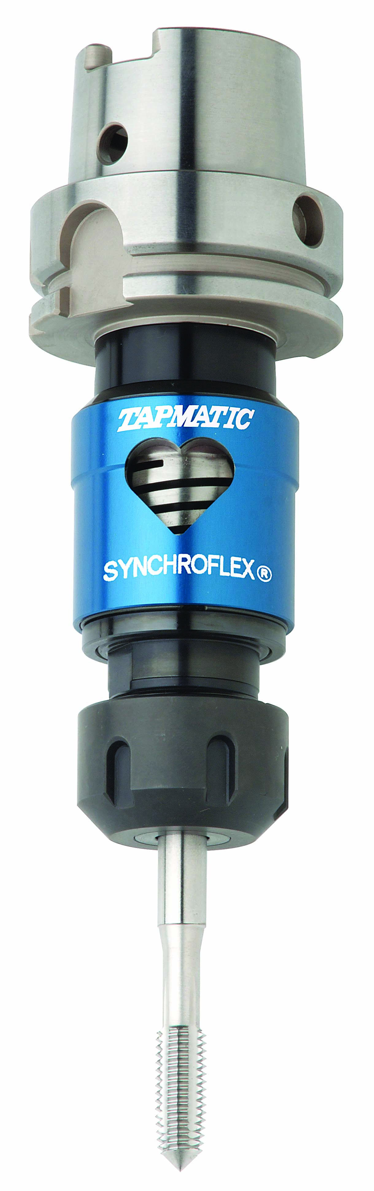
The SynchroFlex tapholder permits a small amount of axial compensation to reduce thrust forces on the tap. Image courtesy of Tapmatic
The correct choice for rigid tapping, he said, is an ER tap collet. Instead of a cylindrical opening, this type of collet has a square opening sized to match the square tap end so it can hold the tap firmly enough to prevent slipping during the tapping process.
“If you are diagnosing a tap problem,” Ford said, “particularly breakage, one of the first things you ask is whether they’re using a tap collet.”
Even if they know about ER tap collets, Stewart said some shops decide not to use them. One reason is that they’re somewhat more expensive than standard ER collets. Additionally, job shops may not have tight tolerance requirements like in the automotive and aerospace industries, so a little slippage could be acceptable. And if a shop isn’t tapping large numbers of holes, it may be able to check every one with a thread gauge.
However, “a company that makes thousands of holes a day cannot check every one,” Stewart said. “So they want the assurance that the tap is not going to slip.”
While a tap can’t slip in an ER tap collet, he said the collet itself can slip during rigid tapping. And if the collet slips, the tap slips despite being held firmly by the collet.
To prevent this, NT USA offers a rigid tapholder called the STM. Instead of being held by the collet, the square tap end is held firmly by a square opening in the STM itself. On the downside, a tap held by the STM probably will break instantly if the threaded end becomes jammed in a workpiece. But as Stewart explains it, the alternative could be undetected slippage of an ER tap collet that results in many bad parts being machined.
“If the tap breaks, the machine would detect that, so there may be one bad part,” he said. “But if the tap keeps slipping, (a shop) may need to scrap hundreds of
workpieces.”
STM holders also allow users to easily adjust the projection length of the tap by turning an outer guide ring. This is helpful in situations where manufacturers regrind taps to save money instead of replacing them after each job. Firms that do this, however, always need to have the same tap projection length from the gauge line of the holder.
“If they grind it down 2 mm (0.08"), they need to make it stick out 2 mm longer to make it the exact same gauge length,” Stewart said. “If you use a collet with the square built in, you drop the tap into it, and you can’t adjust anything. But our square moves up and down inside the holder, so you can adjust the tap projection length to compensate if you’re grinding it down.”
Not Completely Rigid
Although a totally rigid holder has a number of advantages over a floating holder, there’s also a downside: Unlike a floating holder, a rigid one doesn’t compensate for force applied to a tap during a rigid tapping cycle. This force stems from the fact that there is always a small discrepancy between the tap lead programmed into the machine controller and the lead actually ground into the tap. But there’s no give in a totally rigid holder to mitigate the effects of this discrepancy. As a result, Johnson said, a heavy thrust load is applied to the tap, which makes it wear more quickly and can adversely affect thread quality.
So for those using a synchronous machine for tapping, Ford recommends the use of a synchronous-style holder, such as his company’s Synchro Chuck. Inside these holders are objects like springs, washers and rubber gaskets, which allow a very small amount of movement — far less than that permitted by a floating holder but enough to absorb forces generated by rapid stopping and reversing while rigid tapping. He said this can yield as much as 25% more tool life and improved thread finish compared with tapping done by completely rigid holders. Some also believe that synchronous holders allow slightly faster spindle speeds during the tapping process, he said.
Inside the SynchroFlex synchronous holder from Tapmatic, the force-absorbing mechanism is a precision flexure like a machine spring. Johnson said the small amount of give provided by the flexure makes a big difference in tool life.
“You typically get double the tap life compared to a solid holder,” he said.
Contact Details
Contact Details

Contact Details

Related Glossary Terms
- chuck
chuck
Workholding device that affixes to a mill, lathe or drill-press spindle. It holds a tool or workpiece by one end, allowing it to be rotated. May also be fitted to the machine table to hold a workpiece. Two or more adjustable jaws actually hold the tool or part. May be actuated manually, pneumatically, hydraulically or electrically. See collet.
- collet
collet
Flexible-sided device that secures a tool or workpiece. Similar in function to a chuck, but can accommodate only a narrow size range. Typically provides greater gripping force and precision than a chuck. See chuck.
- computer numerical control ( CNC)
computer numerical control ( CNC)
Microprocessor-based controller dedicated to a machine tool that permits the creation or modification of parts. Programmed numerical control activates the machine’s servos and spindle drives and controls the various machining operations. See DNC, direct numerical control; NC, numerical control.
- endmill
endmill
Milling cutter held by its shank that cuts on its periphery and, if so configured, on its free end. Takes a variety of shapes (single- and double-end, roughing, ballnose and cup-end) and sizes (stub, medium, long and extra-long). Also comes with differing numbers of flutes.
- feed
feed
Rate of change of position of the tool as a whole, relative to the workpiece while cutting.
- grinding
grinding
Machining operation in which material is removed from the workpiece by a powered abrasive wheel, stone, belt, paste, sheet, compound, slurry, etc. Takes various forms: surface grinding (creates flat and/or squared surfaces); cylindrical grinding (for external cylindrical and tapered shapes, fillets, undercuts, etc.); centerless grinding; chamfering; thread and form grinding; tool and cutter grinding; offhand grinding; lapping and polishing (grinding with extremely fine grits to create ultrasmooth surfaces); honing; and disc grinding.
- outer diameter ( OD)
outer diameter ( OD)
Dimension that defines the exterior diameter of a cylindrical or round part. See ID, inner diameter.
- pitch
pitch
1. On a saw blade, the number of teeth per inch. 2. In threading, the number of threads per inch.
- shank
shank
Main body of a tool; the portion of a drill or similar end-held tool that fits into a collet, chuck or similar mounting device.
- tap
tap
Cylindrical tool that cuts internal threads and has flutes to remove chips and carry tapping fluid to the point of cut. Normally used on a drill press or tapping machine but also may be operated manually. See tapping.
- tapping
tapping
Machining operation in which a tap, with teeth on its periphery, cuts internal threads in a predrilled hole having a smaller diameter than the tap diameter. Threads are formed by a combined rotary and axial-relative motion between tap and workpiece. See tap.
- threading
threading
Process of both external (e.g., thread milling) and internal (e.g., tapping, thread milling) cutting, turning and rolling of threads into particular material. Standardized specifications are available to determine the desired results of the threading process. Numerous thread-series designations are written for specific applications. Threading often is performed on a lathe. Specifications such as thread height are critical in determining the strength of the threads. The material used is taken into consideration in determining the expected results of any particular application for that threaded piece. In external threading, a calculated depth is required as well as a particular angle to the cut. To perform internal threading, the exact diameter to bore the hole is critical before threading. The threads are distinguished from one another by the amount of tolerance and/or allowance that is specified. See turning.
- tolerance
tolerance
Minimum and maximum amount a workpiece dimension is allowed to vary from a set standard and still be acceptable.
- turning
turning
Workpiece is held in a chuck, mounted on a face plate or secured between centers and rotated while a cutting tool, normally a single-point tool, is fed into it along its periphery or across its end or face. Takes the form of straight turning (cutting along the periphery of the workpiece); taper turning (creating a taper); step turning (turning different-size diameters on the same work); chamfering (beveling an edge or shoulder); facing (cutting on an end); turning threads (usually external but can be internal); roughing (high-volume metal removal); and finishing (final light cuts). Performed on lathes, turning centers, chucking machines, automatic screw machines and similar machines.
Author

William Leventon is a contributing editor to Cutting Tool Engineering magazine. Contact him by phone at 609-920-3335 or via email at [email protected].
Contributors
NT USA Corp.
615-771-1899
www.nttoolusa.com
Tapmatic Corp.
800-854-6019
www.tapmatic.com
YG-1 Tool (USA) Co.
800-765-8665
www.yg1usa.com
