In recent years, monolithic machined aluminum components have been replacing sheet metal assemblies throughout the aerospace industry. The monolithic structures are lighter, less expensive and stronger than their conventional sheet metal counterparts. Machining the components requires fewer special tools, fewer hand operations and less assembly time.
R&D in this area began in the 1970s with testing of high-speed machining theories. At that time, ballistic machining tests, where the cutting tool shot past the workpiece as a projectile, made it clear that solid-carbide tools would be quite capable of surviving the cutting temperatures when machining aluminum. However, a new class of machine tools would be required to support those cutting tools.
Courtesy of S. Smith
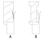
Figure 1A: Machining a thin wall occurs as the tool tip removes material at the base of the wall, where the wall is stiff.
Figure 1B: To avoid cutting through a thin wall, apply a tool with its cutting teeth removed from the portions of the tool where no machining is intended.
In the 1980s, as spindles and machine tools became faster, the development of reliable chatter prediction tools began to dominate HSM research, and the drive to simplify the tools for chatter avoidance became a powerful force.
In the 1990s, it became evident that there was growing value in the ability to produce thin structures by machining, and research shifted to the cutting tool geometries and machining strategies required to manufacture thin components. By the late 1990s and early 2000s, it was possible to machine exquisitely thin part features, and machined monolithic components are still on the rise.
There are three basic rules for machining thin components.
Rule No. 1. Select stable machining conditions. Chatter must be completely avoided. Several past columns have dealt with the stability lobe diagram and the measurements and tests required to ensure stable machining. High spindle speeds are not required to create thin components because there is no secret reduction of cutting forces or temperatures at high speeds. Thin monolithic components can be made using conventional equipment. However, as spindle speed increases, the stable zones in the stability lobe diagram get larger, and higher metal-removal rates are possible.
Rule No. 2. Use a special machining strategy. A thin wall is flexible at the top but not at the bottom. A machining strategy must be selected to cut the thick part, leaving the thin part. To make a thin wall, machining proceeds layer by layer from the top of the wall to the bottom. On each layer, the wall is cut to its finished thickness. Machining occurs as the tool tip removes material at the base of the wall, where the wall is stiff (Figure 1A). Once each layer is completed, that portion of the wall should not be machined again. A conventional strategy of roughing the entire wall almost to the finished dimension, followed by a finishing pass, will not work.
Rule No. 3. Use relieved shank tooling. As shown in Figure 1A, as machining progresses down the wall, the portion of the wall left becomes taller and more flexible. At some point, the impact of the cutting teeth at the bottom of the wall causes the wall to vibrate. When that happens, the top of the vibrating wall makes contact with the teeth higher on the tool, DOC increases and chatter occurs. The vibration may be quite severe, and the tool shank can even cut through the thin wall. The solution is to apply a tool with its cutting teeth removed from the portions of the tool where no machining is intended (Figure 1B). The thin wall still vibrates, but there is no cutting tool for the vibrating wall to touch. Relieved-shank, solid-carbide endmills are available for this operation.
How thin can the walls be? The short answer is thinner than you want. Thinner and taller walls require deeper relief on the tool, smaller DOCs per pass and more passes. Part manufacturers have made walls thinner than 0.002 ". The height of the wall is limited by the thickness of the available stress-relieved plate stock, which is currently about 6 ". CTE
About the Author: Dr. Scott Smith is a professor at the William States Lee College of Engineering, University of North Carolina at Charlotte, specializing in machine tool structural dynamics. Contact him via e-mail at [email protected].
Related Glossary Terms
- chatter
chatter
Condition of vibration involving the machine, workpiece and cutting tool. Once this condition arises, it is often self-sustaining until the problem is corrected. Chatter can be identified when lines or grooves appear at regular intervals in the workpiece. These lines or grooves are caused by the teeth of the cutter as they vibrate in and out of the workpiece and their spacing depends on the frequency of vibration.
- relief
relief
Space provided behind the cutting edges to prevent rubbing. Sometimes called primary relief. Secondary relief provides additional space behind primary relief. Relief on end teeth is axial relief; relief on side teeth is peripheral relief.
- shank
shank
Main body of a tool; the portion of a drill or similar end-held tool that fits into a collet, chuck or similar mounting device.
Author
Dr. Scott Smith is a professor and chair of the Department of Mechanical Engineering at the William States Lee College of Engineering, University of North Carolina at Charlotte, specializing in machine tool structural dynamics. Contact him via e-mail at [email protected].

Click on the author to view all of their articles!