Thread milling, simplified
While thread milling is a well-established process, some machine shops are still afraid to try it, fearing it is too complicated. "Thread milling is not a big mystery, but some shops are hesitant to do it," said Joe Mazzenga, sales manager for J.M. Sales - USA, Troy, Mich., which offers solid-carbide and indexable-insert thread mills.
While thread milling is a well-established process, some machine shops are still afraid to try it, fearing it is too complicated. “Thread milling is not a big mystery, but some shops are hesitant to do it,” said Joe Mazzenga, sales manager for J.M. Sales – USA, Troy, Mich., which offers solid-carbide and indexable-insert thread mills. “In reality, we can set up a customer to successfully thread mill fairly easily—as long as they have the right tooling.”
Thread milling requires a machining center capable of helical interpolation, which requires three axes of simultaneous movement. Two axes perform circular interpolation while the third moves perpendicular to the circular plane. Most CNC machines built in the last 10 to 15 years have this capability.
Courtesy of KOMET
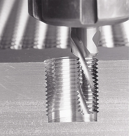
The same KOMET JEL thread mill cutting two different diameter holes—an M10×1.5 (left) and an M18×1.5.
“Rarely do I run across someone who can’t do it,” noted Jim Hartford, vice president of Advent Tool & Manufacturing Inc., Antioch, Ill. Advent manufactures single- and multiple-flute inserted thread mills and solid-carbide thread mills.
The inserted type with multiple flutes is typically for thread milling holes ¾ ” in diameter or larger because there has to be enough room for the tool body and inserts. Smaller inserted thread mills are available but they usually have only one or two flutes.
“In a lot of cases, when you get into holes ¾ ” and smaller you can still get a 4- or 6-flute solid cutter in there to do the job,” Hartford said. “With the inserted cutter, you could only get possibly one insert in there so your cycle times would be slow. For example, in 316 stainless steel, a single-flute thread mill would take 40 to 45 seconds to thread a hole. With a 4-flute, solid-carbide thread mill, it would take 6 to 8 seconds.”
Comparing solid-carbide and inserted thread mills at larger diameters, solid carbide is generally better for high production because it enables faster cycle times.
“While both solid-carbide and inserted thread mills are suited for larger diameter holes, it can be advantageous to use smaller solid-carbide tools as they can typically run at higher feed rates,” said Wolfgang Ruff, vice president of engineering for KOMET of America Inc., Schaumburg, Ill. “For instance, if you have an M80×1.5 thread, you can run a 50mm-dia. inserted thread mill, which would have five cutting edges. You can also choose a 20mm-dia. solid-carbide thread mill, which will also have five cutting edges, but will run at more than twice the feed rate, effectively cutting the production time for each hole by half. This makes a huge difference for large production runs.”
Inserted thread mills can be good for smaller job shops with small production runs. One tool body can use multiple replaceable inserts with different thread forms, so it is more versatile and less expensive overall.
“They operate the same, but there is the cost difference,” Hartford said. “The tool body would cost about $300 to $450, but the inserts are only about $30 when replacement is needed. With the solid-carbide thread mill, the entire tool needs to be replaced at a $200 to $300 price tag. Also, it is easier for an operator to change an insert than to change an entire tool and requalify it.”
KOMET’s Ruff pointed out that inserts must be precisely positioned in the pockets. “If they are not, there is a mismatch from one insert to another and you cannot produce the proper thread.” KOMET offers solid-carbide thread mills as standard tools and inserted ones as specials.
Solid-carbide and inserted thread mills come in helical- and straight-flute designs. Helical flutes reduce cutting pressure by distributing the cutting pressure along the flute.
“We use the helical almost exclusively,” Mazzenga said. “With a helical-flute cutter, you get a much smoother, quieter cut because the engagement of the teeth is spread over a greater range. On a straight-flute cutter, all the teeth on a given flute engage at the same time. This creates a greater amount of radial pressure, causing chatter and deflection.”
Nevertheless, straight flutes have a geometry suited for hard materials from 55 to 64 HRC. “The rake angle on a straight flute is constant,” Mazzenga noted.
Multiple vs. Single Form
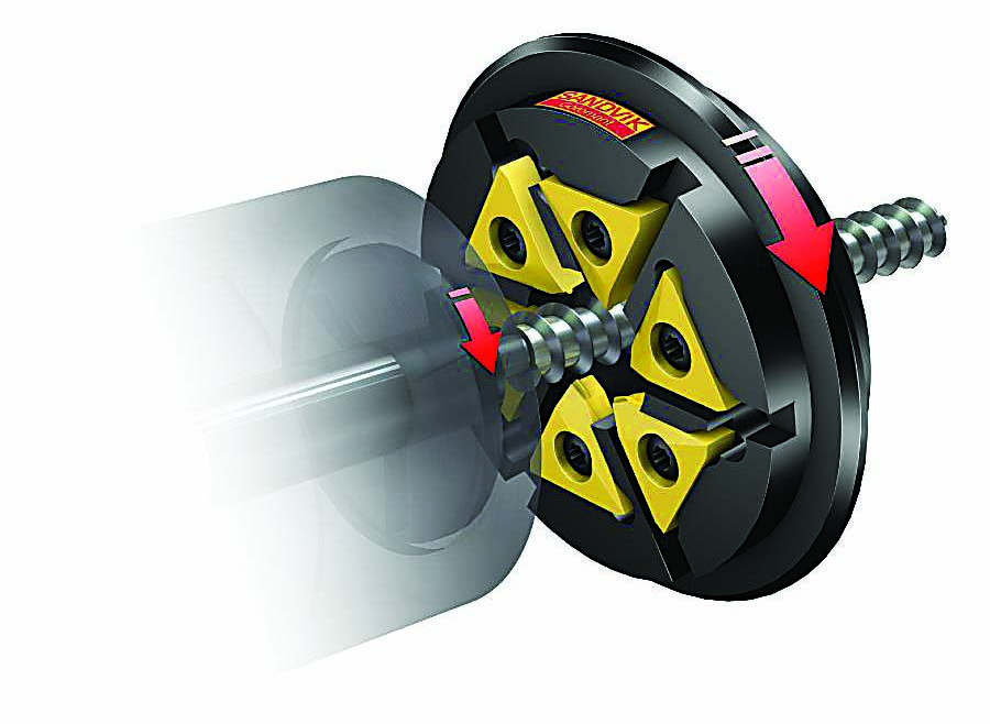
Most thread mills, solid carbide or inserted, are multitooth tools. The teeth are arranged parallel, rather than helically like a tap. Multitooth thread mills cut the full depth of the thread in a single rotation around the hole.
Courtesy of J.M. Sales
J.M. Sales offers its Quattro indexable-insert thread mill (left), GFT thread mill with three rings of teeth for small diameters and 3 diameters deep (second from left), BGFS-W drill/thread mill for steels and titanium (second from right) and BGFS-H drill/thread mill for hardened steels (right).
One multitooth thread mill can cut threads of the same pitch in a range of diameters. This is because the diameter is determined by the CNC toolpath instead of the tool (as with a tap). “With a fixed pitch, the multiform tool can cut any 20-pitch thread, whether it is ¼-20, ¾-20 or 2″-20, as long as it can fit in the hole,” said Stephan Francescone, production manager for Harvey Tool Co. LLC, Rowley, Mass., which makes single- and multiple-form solid-carbide thread mills.
“The multiform thread mill is fast because all those peaks and valleys are cutting at the same time to create the thread,” said Jeff Davis, vice president of engineering for Harvey Tool. “The downside is that you’re locked into the pitch because of those peaks and valleys. Anytime you see more than one triangular thread form on a tool, you have a fixed-pitch situation.” Each thread pitch requires a different tool.
In addition to being able to cut any diameter, the advantage of a single-form thread mill is it can cut any thread pitch or a range of thread pitches. However, a single-form thread mill can only cut one thread in a single pass and must move around the hole as many times as there are numbers of threads.
“Even though they have to buy a thread mill for each pitch, larger production shops lean toward a multiform so they have a nice array of tools,” Davis said. “The single-form tools lend themselves more to smaller job shops that want a more flexible tool.”

Courtesy of Harvey Tool
Harvey Tool’s AlTiN-coated thread mills are suited for threading difficult-to-cut materials, ferrous materials, steels and aerospace materials. They are also available with TiB2 coating for aluminum workpieces.
Courtesy of KOMET
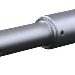
KOMET’s single-form thread mill, typically for deep threads, has replaceable carbide heads.
J.M. Sales – USA’s Mazzenga said his company doesn’t subscribe to the belief that thread mills can be used for any diameter as long as the pitch is the same. “It is somewhat correct, but we don’t define it that loosely,” he said. “Our thread mills are designed to cut the thread on the minor diameter as well as the flank and the crest. Most of our thread mills are manufactured for a specific pitch and diameter.
“We define that thread mill more completely than just 60° included threads (standard thread forms are 60° included),” he continued. “In reality, if you try to make your thread mill as large as possible for a specific thread and don’t compensate that form in the tool itself, you will produce threads that border the thread tolerance boundaries. It is quite possible to make an adjustment on the machine for pitch diameter and then have an oversize minor diameter. We correct the thread form of the tool to allow for this.”
KOMET offers both types of thread mills: those with the so-called “corrected profile” (M16 and under) and those without the corrected profile. When using the latter for larger diameter holes, it is crucial to follow the “2⁄3 concept” where the diameter of the thread mill has to be no larger than 2⁄3 of the hole to maintain the correct pitch for the threads.
Review the print ads from this magazine to continue
This quick advertiser review unlocks the rest of the article and keeps the full-screen reader focused on the ads instead of the page chrome.

MFGAxis Discussion