Reaming titanium is a challenging task, but new tools can give shops an edge as they battle this difficult-to-machine material.
Courtesy of B. Kennedy
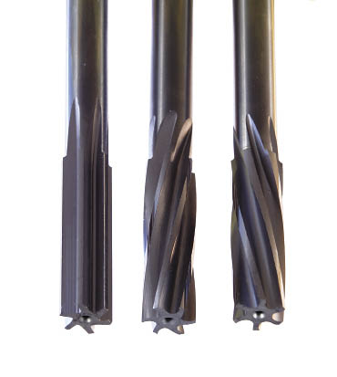
A straight-flute reamer (left) can cut titanium, but helical reamers can provide freer cutting action and can direct chip flow. The cutting angle of the flutes of a left-hand helix reamer (right) is not as positive or acute as a right-hand helix reamer (center), and therefore does not cut as freely. However, the left-hand helix tool forces chips forward and out of a through-hole. In a blind-hole, the flutes of the right-hand helix tool lifts chips up and out of the hole.
As anyone who cuts metal for a living knows, holemaking is much more than simply making a hole. Brian Hurd, sales manager, North America for toolmaker Mapal Inc., outlined the basic holemaking steps: “You drill to remove material, you bore to establish the position of the hole and you ream to establish the size.”
The last step, reaming, usually is the key to a hole’s functionality. As a hole finishing operation, reaming involves removing a small amount of material, with emphasis on generating a smooth and uniform surface finish within the bore.
Among the crucial factors in determining the best tools and parameters for productive reaming are the properties of the workpiece material. With its mix of unique characteristics, titanium can make reaming much more than simply finishing a hole.
Lighter, Stronger
An excellent strength-to-weight ratio is one of titanium’s signature properties. While it is about 60 percent of the density of steel, titanium also possesses tensile strength as high or higher than most steel alloys. Because it has perhaps twice the elasticity of typical steels, titanium provides excellent durability and fatigue resistance in structural applications. A stable, continuous oxide layer spontaneously forms on the surface of titanium, creating a protective layer that provides corrosion resistance and makes the material inert and biocompatible. The melting point of titanium is about 400° F higher than steel and 2,000° F higher than aluminum.
Increased demand for precision hole finishing accompanies the expanding list of titanium applications. However, the same properties that make titanium so useful also make it difficult to machine. Although initial cutting forces are only slightly higher than those involved in cutting steel of equivalent hardness, the material tends to workharden. And, despite its chemical inertness at room temperatures, titanium has a strong tendency to alloy with other materials at high cutting temperatures. The material’s elasticity, a benefit in resisting fatigue failure in structural applications, becomes a liability when machining; the workpiece material actually moves away from the cutting edge as it approaches, then springs back.
Relative to metalcutting in general and reaming in particular, one of titanium’s most significant properties is its poor ability to conduct heat. According to Niagara Cutter, when machining steel, 75 percent of the heat generated is transferred into the cut chips, 15 percent into the cutting edge and 10 percent into the workpiece material. When machining titanium, only 25 percent of the heat is carried away by the chips while 15 percent is absorbed by the part and 60 percent is transferred to the cutting edge.
The concentrated heat significantly reduces tool life. The high-temperature reactivity of titanium leads to diffusion of material between the tool and part, accelerating a tool’s crater and notch wear. The light cuts characteristic of reaming demand a careful balance between taking too much stock and distorting hole dimensions and surface finish, or taking too light a cut and pushing rather than cutting the material, generating friction, more heat and a workhardened surface.
Courtesy of B. Kennedy
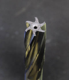
Cooling the cut when machining titanium is crucial, so reamers engineered for machining titanium generally feature axial through-holes to direct coolant to the cutting zone.
The size of the preceding drill or boring tool determines the amount of stock left for reaming. B.J. Grizzle, vice president of sales for toolmaker Superion Inc., Xenia, Ohio, said: “For titanium, the stock removal we recommend is 3 percent of the bore diameter or less. Typically, if there are problems with finish, then we start looking at taking a little less material. However, care must be taken to avoid taking too little material and pushing the material. You’ve definitely got to find the happy medium.”
Claude Farrington, plant manager at Quakertown, Pa,. job shop John Prosock Machine Inc., said when reaming titanium bone screw prototypes, the shop found success by “leaving as little material as possible” for the reamer to cut. Where perhaps 0.011 " excess material was typical when reaming aluminum or steel, the shop left only 0.0005 " to 0.001 " when reaming titanium, and employed dark cutting oil, a heavy-duty, sulfur-containing fluid used to lubricate and cool the cut.
Coolant Required
Considering titanium’s poor heat-transfer characteristics, cooling the cut is crucial. Peter Diamantis, plant manager for Amamco Tool, Duncan, S.C., said, “It’s very difficult to work with titanium without some sort of coolant.” He noted that geometry on reamers for titanium made by Amamco is practically the same as any other metal, “but we incorporate coolant holes in the tool to deliver the coolant along the cutting perimeters.” Water-based coolants work well when machining titanium, and soluble oils offer excellent lubricity, according to coolant maker Cimcool. Titanium supplier Timet says sulfo-chlorinated oils appear to be the best cutting fluids for titanium, but water-based oil emulsions are also used successfully, particularly with softer, unalloyed titanium grades.
Cutting speed is the chief heat generator when machining titanium. John Forrest, vice president and sales manager, Tool Alliance, Huntington Beach, Calif., said: “As with a lot of workhardening materials like Inconel and some austenitic grades of stainless alloys, speed and heat can make things much more difficult. On those materials, you want to be on the low side of tool supplier recommendations when it comes to speed, and on the high side when it comes to feed. All the speed does is create more heat, which makes it more difficult to cut and creates workhardening.”
Titanium supplier Supra Alloys agreed with this assessment. Tool tip temperatures are affected more by cutting speed than by any other single variable, according to the company. In a typical case, a change from 20 to 150 sfm with carbide tools increased tool tip temperature from 800° F to 1,700° F. On the other hand, the company stated, feed rates do not affect temperature to as great an extent as speed. In the same case, a change in feed rate from 0.002 ipr to 0.020 ipr increased tool tip temperature only 300° F.
Therefore, if a shop is pursuing higher productivity in a titanium reaming operation, toolmakers recommend applying cutting speeds in the low range of recommendations, increasing feed rate until poor surface finish, a distorted hole or poor final size occurs, then backing off the feed until the problem disappears.
Regarding speed and feed recommendations, tool manufacturers emphasize that individual titanium alloys possess widely different machining characteristics. Unalloyed titaniums don’t have the strength of titanium alloys, but their resistance to chemical attack at lower temperatures makes them useful in many corrosive situations. The lack of structural strength, does, however, make them easier to machine than alloyed grades. On the other hand, addition of alloying elements, especially vanadium and chromium, increase a titanium alloy’s strength and fatigue resistance and dictate slower cutting speeds.
For example, while one shop owner said he generally assumes a Ti-6Al-4V workpiece will take three times as long to machine as a steel part, another said a highly alloyed grade such as Ti-5Al-5Mo-5V-3Cr typically requires twice the machining time of Ti-6Al-4V.
Tool Materials and Geometries
Tool materials and geometries must take into account titanium’s gummy and springy nature. “It likes sharp cutting edges, it likes to be sheared, it doesn’t like to be pushed because it will workharden,” Forrest said. “We try to cut this material with as sharp an edge as possible so we shear it more effectively.”
Bill Lahr, tooling engineer at Alvord-Polk Inc., Millersburg, Pa., said titanium generally doesn’t require special reamer geometries, and “if it is a HSS tool, we use a M-42 cobalt grade because of its resistance to heat, higher red hardness, if you will.” According to titanium supplier Timet, while in many cases HSS reamers are satisfactory, carbide reamers allow higher surface speeds or longer tool life.
As for flute geometry, Forrest said helical reamers are preferred over straight-flute reamers, “because the action of the helix is going to give you a little freer cutting condition. Plus, if it’s a through-hole, a left-hand helix will drive the chips and heat forward. The downside is that the left-hand helix doesn’t provide a real positive angle at the chamfer and therefore is not as free cutting. In a blind-hole, a right-hand helix will provide a freer cutting condition, as well as lift the chips up and hopefully out. It gives you a more acute angle at the cutting edge, making it freer cutting.” In addition, the angled path of a helical reamer flute can help minimize the impact of cross-holes and other interruptions in the bore being reamed.
Hurd of Port Huron, Mich.-based Mapal noted that a reamer features circular lands or guide margins that direct the cutting edge through the bore, but because they rub on the side of the hole they can create additional heat. For titanium, he said the guide margins would be narrower than they would be when machining steel or cast iron.
Courtesy of B. Kennedy
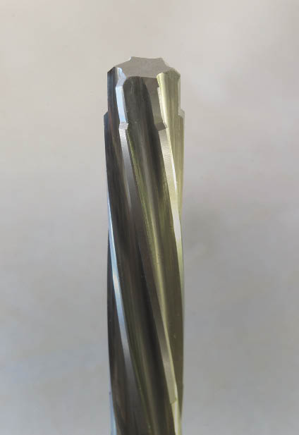
In some situations where part alignment is critical, predrilled holes are left undersized to be reamed at assembly. In materials such as titanium, stock-removal requirements may be too great for a standard reamer so a drill-reamer or a step reamer (pictured) opens and finishes the hole in one pass.
In the case of replaceable-blade reamers, tool body torsion generated by cutting pressure on the insert pushes guide pads on the body against the bore ID, positioning the blade to ream the bore. Managing the relationship between the blade and pad is different with titanium than with other materials, according to Hurd. When reaming aluminum, typically “you would set the diamond insert only about 3µm to 5µm above the guide pad,” he said. Because diamond tools do not wear much when cutting aluminum, the pad/blade relationship would change minimally over the life of the tool. However, “if you tried to do that in titanium, you would have so much insert wear so quickly that you would eventually seize up the guide pads,” because the insert would quickly wear down to the height of the guide pads, Hurd said.
Mapal solves the problem by putting a stabilizing and guide feature called an “F chamfer” on the blade. The chamfer resembles a secondary cutting angle, Hurd said, and “basically hones the sharp edge of the insert so that the wear isn’t quite so pronounced in the beginning of the tool life. You don’t get a sudden drop in size through the first few parts, and you get a little more consistency in a high-abrasion situation, such as reaming titanium.” For reaming titanium, the insert would be set about 8µm to 10µm above the guide pad.
Stack Strategies
Amamco’s Diamantis noted that many aerospace manufacturers drill and ream with one tool to eliminate the two-step drill-then-ream process. Even more challenging than reaming titanium alone is dealing with stacked combinations of titanium and other materials. “Because titanium is hard, when you stack it with a softer material like aluminum or a composite, the titanium chips tend to scar the walls of the softer material. Depending where the titanium is in the stack, you have to construct the direction of your flutes to eliminate the scarring.”
Diamantis described reaming a through-hole in a titanium sandwich stack, with the aluminum as the “bread,” where it would be beneficial to use the flute helix to cut downwards (left-hand helix applied in a right-hand cut) and push the chips downward. “The reamer in a sense will be cleaning out the hole behind the chips,” he said. “If you used a regular [right-hand helix] reamer, you would be pulling the chips over the newly reamed area, thus scarring the walls of the softer material.” He added that “it gets complicated when you cannot down-cut because of clearance constraints. Then, we have to build the tool flutes to encase the chips and keep them from scarring the walls of the hole.”
Superion Products’ Grizzle provided another approach to consolidating hole-finishing operations. For aerospace applications, Superion offers boring reamers to true a drilled hole position in a workpiece. “Typically, a standard reamer will follow the existing hole, whereas a boring reamer is designed to align the hole as it is reamed.” In materials such as titanium, he said, boring reamers are generally used “more as roughers to get the hole straight, followed by a finisher to finish to size and create the surface finish.”
The Hole System
In addition to cutting tool considerations and application parameters, other reaming system elements must also be controlled to achieve optimal hole quality and consistency. Alignment of the machine spindle and the workpiece is crucial. A lack of concentricity between the tool and workpiece can produce chatter during reaming, tool marks during retraction and a conical, eccentric or oversize bore.
The hole being reamed essentially guides the reaming tool, so a straight, concentric drilled hole is a critical part of the reaming system. Bill Shaffer, executive vice president of microedge preparation provider Conicity Technologies LLC, Cresco, Pa., said: “A reamed hole is only going to be as good as the hole that it finishes. A drill with blunt corners will compress the workpiece material instead of cutting it. That workhardens the sides of the hole, maybe only a few microns deep.” The result is accelerated wear of the reamer’s cutting edges (see sidebar on page 56).
For many shops, machining titanium is intimidating. Performing a precision operation like reaming adds to the angst. However, knowledge of titanium’s distinctive properties and the effect they have on the cutting tool can be a great help in recognizing what not to do when working with the lightweight wonder metal. Then, when the “don’ts” are covered, the “do’s” can be applied to boost productivity when reaming titanium. CTE

Courtesy of Conicity Technologies
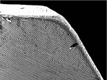
A dead-sharp new reamer edge (top) lacks strength because it has numerous microscopic chips and flaws that concentrate cutting forces and accelerate wear. The tool dulls quickly, creates friction and heat and undersized reamed holes result. A 0.0004 " engineered microgeometry edge treatment on the leading edge angle of a reamer’s cutting edge (bottom) increases edge strength and delays cutting edge breakdown, according to Conicity Technologies.
When reamers go bad
The most common failure mode for a reamer is not widely understood, according to Bill Shaffer of Conicity Technologies LLC. “Generally, a reamer is used until it begins to cut undersize,” he said. “Then the tool’s lead angles are reground, and it is put to use again until the resulting hole is again measuring undersize. It’s never explained how the reamer can cut undersize when the OD of the reamer is still on size, and how simply regrinding the front of the tool gets it back cutting on size again.”
Shaffer said the loss of hole size is directly related to the breakdown of the cutting edges on the tool’s leading edge. As the tool cuts, gradual dulling of the cutting edge incrementally increases tool pressure and heat. As the cutting edge continues to decay, more heat is generated. The heat causes the workpiece material to expand while the tool is in the hole. “But when the reamer is extracted, the part cools and the hole size decreases,” Shaffer said.
Keeping tools sharp eliminates the problem. But a brand-new, dead-sharp cutting edge lacks edge strength because it has numerous microscopic chips and flaws that concentrate cutting forces and accelerate wear. The tool dulls quickly, creates friction and heat and produces undersized reamed holes.
To remove the tiny cutting edge flaws and make the edge uniform, Conicity Technologies has developed edge prep systems that produce a hone with precisely controlled size, shape and distribution. The company calls the edge preparation an engineered microgeometry. A CNC machine precisely applies the EMG to critical areas of the tool. Shaffer claims the machine can consistently control the edge preparation’s size on all tool edges.
A 0.0004 " EMG on the leading edge of a reamer’s cutting edge increases edge strength by perhaps five to eight times, Shaffer said. The increased strength effectively delays the eventual breakdown of the cutting edge on the front flank of the tool. The edge remains intact longer, delaying heat buildup and the advent of undersized holes. The result, Shaffer said, is more reamed holes between regrindings. “Done the same way every time, holding the edge prep size to 0.0001 ", tool life on a reamer will be consistent and repeatable. It will increase anywhere from at least three times to as many as 20 times,” he said.
—B. Kennedy
Contributors
Alvord-Polk Inc.
(800) 441-2751
www.alvordpolk.com
Amamco Tool
(800) 833-2239
www.amamcotool.com
Conicity Technologies
(877) 752-6132
www.conicity.com
John Prosock Machine Inc.
(215) 804-0321
www.jprosock.com
Mapal Inc.
(810) 364-8020
www.mapal.us
Superion Inc.
(937) 374-0034
www.superioninc.com
Tool Alliance
(800) 854-2431
www.toolalliance.com
Contact Details

Contact Details
Contact Details
Contact Details
Contact Details

Related Glossary Terms
- alloys
alloys
Substances having metallic properties and being composed of two or more chemical elements of which at least one is a metal.
- backing
backing
1. Flexible portion of a bandsaw blade. 2. Support material behind the cutting edge of a tool. 3. Base material for coated abrasives.
- blind-hole
blind-hole
Hole or cavity cut in a solid shape that does not connect with other holes or exit through the workpiece.
- boring
boring
Enlarging a hole that already has been drilled or cored. Generally, it is an operation of truing the previously drilled hole with a single-point, lathe-type tool. Boring is essentially internal turning, in that usually a single-point cutting tool forms the internal shape. Some tools are available with two cutting edges to balance cutting forces.
- boring cutter ( or boring tool)
boring cutter ( or boring tool)
Cutting tool mounted in a boring bar (the holder) that enlarges a cored or drilled hole. May be a single-point or multiple-cutting-edge tool. Can be adjustable.
- chatter
chatter
Condition of vibration involving the machine, workpiece and cutting tool. Once this condition arises, it is often self-sustaining until the problem is corrected. Chatter can be identified when lines or grooves appear at regular intervals in the workpiece. These lines or grooves are caused by the teeth of the cutter as they vibrate in and out of the workpiece and their spacing depends on the frequency of vibration.
- clearance
clearance
Space provided behind a tool’s land or relief to prevent rubbing and subsequent premature deterioration of the tool. See land; relief.
- computer numerical control ( CNC)
computer numerical control ( CNC)
Microprocessor-based controller dedicated to a machine tool that permits the creation or modification of parts. Programmed numerical control activates the machine’s servos and spindle drives and controls the various machining operations. See DNC, direct numerical control; NC, numerical control.
- coolant
coolant
Fluid that reduces temperature buildup at the tool/workpiece interface during machining. Normally takes the form of a liquid such as soluble or chemical mixtures (semisynthetic, synthetic) but can be pressurized air or other gas. Because of water’s ability to absorb great quantities of heat, it is widely used as a coolant and vehicle for various cutting compounds, with the water-to-compound ratio varying with the machining task. See cutting fluid; semisynthetic cutting fluid; soluble-oil cutting fluid; synthetic cutting fluid.
- corrosion resistance
corrosion resistance
Ability of an alloy or material to withstand rust and corrosion. These are properties fostered by nickel and chromium in alloys such as stainless steel.
- cutting speed
cutting speed
Tangential velocity on the surface of the tool or workpiece at the cutting interface. The formula for cutting speed (sfm) is tool diameter 5 0.26 5 spindle speed (rpm). The formula for feed per tooth (fpt) is table feed (ipm)/number of flutes/spindle speed (rpm). The formula for spindle speed (rpm) is cutting speed (sfm) 5 3.82/tool diameter. The formula for table feed (ipm) is feed per tooth (ftp) 5 number of tool flutes 5 spindle speed (rpm).
- diffusion
diffusion
1. Spreading of a constituent in a gas, liquid or solid, tending to make the composition of all parts uniform. 2. Spontaneous movement of atoms or molecules to new sites within a material.
- edge preparation
edge preparation
Conditioning of the cutting edge, such as a honing or chamfering, to make it stronger and less susceptible to chipping. A chamfer is a bevel on the tool’s cutting edge; the angle is measured from the cutting face downward and generally varies from 25° to 45°. Honing is the process of rounding or blunting the cutting edge with abrasives, either manually or mechanically.
- fatigue
fatigue
Phenomenon leading to fracture under repeated or fluctuating stresses having a maximum value less than the tensile strength of the material. Fatigue fractures are progressive, beginning as minute cracks that grow under the action of the fluctuating stress.
- fatigue resistance
fatigue resistance
Ability of a tool or component to be flexed repeatedly without cracking. Important for bandsaw-blade backing.
- feed
feed
Rate of change of position of the tool as a whole, relative to the workpiece while cutting.
- flutes
flutes
Grooves and spaces in the body of a tool that permit chip removal from, and cutting-fluid application to, the point of cut.
- hardness
hardness
Hardness is a measure of the resistance of a material to surface indentation or abrasion. There is no absolute scale for hardness. In order to express hardness quantitatively, each type of test has its own scale, which defines hardness. Indentation hardness obtained through static methods is measured by Brinell, Rockwell, Vickers and Knoop tests. Hardness without indentation is measured by a dynamic method, known as the Scleroscope test.
- high-speed steels ( HSS)
high-speed steels ( HSS)
Available in two major types: tungsten high-speed steels (designated by letter T having tungsten as the principal alloying element) and molybdenum high-speed steels (designated by letter M having molybdenum as the principal alloying element). The type T high-speed steels containing cobalt have higher wear resistance and greater red (hot) hardness, withstanding cutting temperature up to 1,100º F (590º C). The type T steels are used to fabricate metalcutting tools (milling cutters, drills, reamers and taps), woodworking tools, various types of punches and dies, ball and roller bearings. The type M steels are used for cutting tools and various types of dies.
- inner diameter ( ID)
inner diameter ( ID)
Dimension that defines the inside diameter of a cavity or hole. See OD, outer diameter.
- lubricity
lubricity
Measure of the relative efficiency with which a cutting fluid or lubricant reduces friction between surfaces.
- metalcutting ( material cutting)
metalcutting ( material cutting)
Any machining process used to part metal or other material or give a workpiece a new configuration. Conventionally applies to machining operations in which a cutting tool mechanically removes material in the form of chips; applies to any process in which metal or material is removed to create new shapes. See metalforming.
- outer diameter ( OD)
outer diameter ( OD)
Dimension that defines the exterior diameter of a cylindrical or round part. See ID, inner diameter.
- reamer
reamer
Rotating cutting tool used to enlarge a drilled hole to size. Normally removes only a small amount of stock. The workpiece supports the multiple-edge cutting tool. Also for contouring an existing hole.
- red hardness
red hardness
Ability of a cutting tool material to withstand high temperatures at the point of cut without softening and degrading.
- tensile strength
tensile strength
In tensile testing, the ratio of maximum load to original cross-sectional area. Also called ultimate strength. Compare with yield strength.
- through-hole
through-hole
Hole or cavity cut in a solid shape that connects with other holes or extends all the way through the workpiece.
- workhardening
workhardening
Tendency of all metals to become harder when they are machined or subjected to other stresses and strains. This trait is particularly pronounced in soft, low-carbon steel or alloys containing nickel and manganese—nonmagnetic stainless steel, high-manganese steel and the superalloys Inconel and Monel.