Titanium is a reactive metal used for making parts. Other reactive metals include magnesium, hafnium, zirconium and depleted uranium. The reactive metals are pyrophoric, creating potential fire hazards. Special precautionary measures allow managing this problem, such as applying large quantities of cutting fluids, having an argon or nitrogen atmosphere and maintaining a Class D fire extinguisher for emergencies.
Titanium alloys are considered difficult-to-machine metals, especially when facemilling. To manage this problem, the following data should be considered:
• Titanium alloy properties,
• Principal geometry of facemills,
• Suitable cutting tool materials,
• Machining parameters, and
• Coolant application.
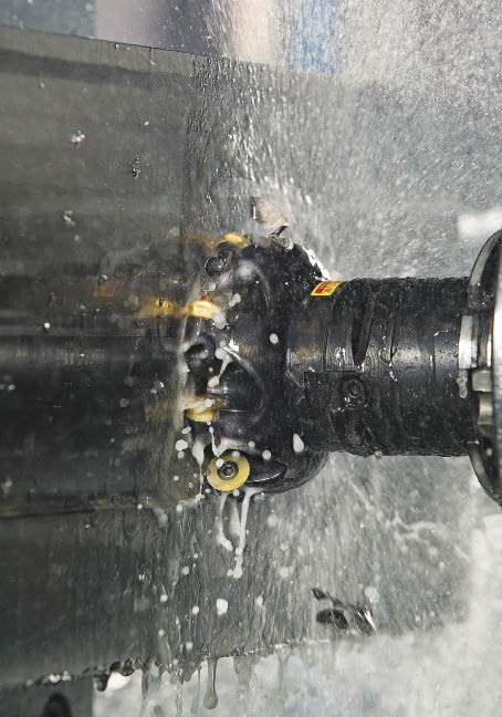
Courtesy of Sandvik Coromant
A Sandvik Coromant CoroMill 300 cutter tooled with round inserts facemills titanium.
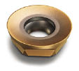
A Sandvik Coromant round insert with a sharp edge (above).
Titanium exists in two crystallographic forms. At room temperature, pure titanium has a hexagonal, close-packed crystal structure known as alpha (α) phase. At about 1,620° F (880° C), this phase transforms to a body-centered cubic structure known as beta (β) phase. The combination of these crystallographic phases through addition of alloying elements and thermomechanical processing is the basis for development of various alpha-beta titanium alloys with predetermined properties.
Ti-6Al-4V (6 percent aluminum and 4 percent vanadium) is an alpha-beta alloy. It is used for making aircraft gas turbine discs and blades and other components where strength at temperatures up to 600° F (315° C) is required.
Ti-6Al-4V Properties
High tensile strength at annealed condition (130,000 psi, or 900 MPa) and low density (4.42 g/cm3, or 0.160 lb/in.3) make Ti-6Al-4V a popular workpiece material.
The low thermal conductivity of Ti-6Al-4V (6.6 W/m×K), which is about 15 percent of AISI 4340 alloy steel’s 44.6 W/m×K, results in high cutting temperatures. About 80 percent of the generated heat goes into the cutting tool rather than dissipating with the evacuated chips. High heat may cause built-up edge, tool chipping or other types of premature tool failure.
Table 1: Mechanical properties of Ti-6Al-4V alloy.
| Ultimate tensile strength | Treatment | Rockwell hardness, HRC | |
| ksi | MPa | ||
|
120 to 130 |
830 to 900 |
Annealed |
35 |
|
130 to 144 |
900 to 990 |
Annealed |
36 |
|
170 |
1,170 |
Aged |
41 |
Cutting speed is the most influential parameter that increases the cutting temperature. Increasing the feed per tooth, or chip load, produces thicker chips, which dissipate more heat than thin chips. That reduces the cutting temperature. A higher metal-removal rate can also be obtained by increasing the feed per tooth when the axial DOC and the radial WOC, or radial engagement, are optimal.
Strength and hardness data of Ti-6Al-4V are shown in Table 1. Its high strength and low thermal conductivity place Ti-6Al-4V among the most difficult-to-machine materials.
Ti-5Al-5V-5Mo-3Cr and Ti-10V-2Fe-3Al are stronger titanium alloys that are becoming more common, but their machinability rating is 50 percent compared to that of Ti-6Al-4V, meaning the cutting speed has to be reduced.
Principal Cutting Geometry
Cutters with positive-negative and double-positive geometries are applied for milling various materials, including titanium alloys. Positive-negative geometry is characterized by positive axial rake angles from 5° to 20° and negative radial rake angles from -2° to -11°. Double-positive geometry is characterized by positive axial rake angles from 5° to 20° and positive radial rake angles from 1° to 14°. Positive-negative geometry milling cutters with an axial rake angle from 5° to 15° are mostly applied for milling Ti-6Al-4V because they generate low cutting forces and consume less power. Most modern milling tools have a positive-negative design. But when considering the insert geometry, it is almost always positive. A cutter is considered positive-positive if its true rake angle is positive.
Climb milling is a common practice when milling titanium alloys. Because the insert enters the workpiece with the maximum chip thickness and exits the cut with a zero chip thickness, friction and rubbing between the insert and workpiece is minimal. Climb milling reduces heat by dissipating it partly into the chip and partly into the insert. With less heat entering the workpiece, workhardening is minimized.
To increase tool life, it’s important to program toolpaths that minimize chip thickness when inserts exit the cut.
Coolant, coolant delivery and coolant pressure influence tool life. By applying high-pressure coolant (1,000 psi) through a tool and directing it at the cutting zone, tool life can be increased up to 100 percent. Using a through-coolant tool minimizes the risk of recutting chips, which also helps increase tool life and process security. Chips often weld onto an insert’s rake face, which puts extra stress on the insert and may cause premature failure. Accurately delivering coolant to the cutting edge ensures chips are flushed away from the insert.
Chemically active fluids transfer heat from the cutting zone and reduce frictional forces between the tool and workpiece. Large quantities of fluid are needed to keep the workpiece and cutting tool cool during machining operations. Water-based coolants incorporating rust inhibitors or water-soluble oils work best for most facemilling operations. Low-viscosity sulfurized and chlorinated oils may be applied when cutting speeds are low. The coolant concentration should be 8 to 12 percent.
Machining parameters recommended by Machining Data Handbook (the traditional method from about 30 years ago) for facemilling alpha-beta titanium alloys are summarized in Table 2.
Milling Cutters, Parameters
Sandvik Coromant Co., Fair Lawn, N.J., offers the CoroMill 300 series of milling cutters with round inserts for roughing and semifinishing titanium alloys. Round inserts are recommended because they provide chip thinning similar to a cutter with a 45° lead angle, which increases the mrr. In addition, as shown in Figure 1, the length of a round insert’s cutting edge (1a) is 75 percent longer than an insert with a 0° lead angle and 24 percent longer than one with a 45° lead angle, so the wear on the round insert spreads out over a longer length. This extends tool life.
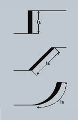
Figure 1: The length of a round insert’s cutting edge (bottom) is 75 percent longer than an insert with a 0° lead angle (top) and 24 percent longer than one with a 45° lead angle (middle), so the wear on the round insert spreads out over a longer length. This extends tool life.
The catalog item number of a popular cutter is RA300-102R38-16H:
Cutter diameter, Dc = 3.386 " (D3 = 4.0 ")
Number of inserts, zn = 8
PVD-coated carbide grade is GC1030 (ISO P30, S15)
Effective (true) rake angle, γoe = 20°
The catalog item number of the round insert for the cutter is R300-1648E-PL 1030:
R300 = product family
16 = insert size, IC (diameter of inscribed circle) = 16mm (0.63 ")
48 = insert thickness, 4.8mm (0.189 ")
E = insert tolerance class, ground edge
PL = positive insert geometry
1030 = carbide grade
Sandvik Coromant recommends the following starting-point cutting parameters when applying the cutter:
Maximum DOC, ap = 0.236 "
WOC, ae = 2.8 "
Feed per tooth, fz = 0.0098 "
Cutting speed, Vc = 210 sfm
Calculating Machining Power
The traditional method of calculating required machining power (Pm) is based on the mrr (Q) and the unit power value for milling (P) provided by Machining Data Handbook. The mrr is calculated by the formula:
Q = ae × ap × fz × zn × n (in.3/min.)
Where ap = 0.300 " and fz = 0.008 " are the values shown in Table 2,
ae = 2.8 " and zn = 0.0098 " are the values described earlier, and
n is a spindle speed calculated by the commonly used formula:
n = 12 × Vc ÷ (π × D3)
Substitution of n in the mrr formula by n from the second formula gives:
Q = 12 × Vc × ae × ap × fz × zn ÷ (π × D3)
Where Vc = 115 sfm is a recommended cutting speed (Table 2), and
D3 = 4.0 " is the diameter of the milling cutter from Sandvik Coromant.
Q = 12 × 115 × 2.8 × 0.3 × 0.008 × 8 ÷ (π × 4.0) = 5.9 in.3/min.
The required machining power calculated by the traditional method is shown in the following formula:
Pm = Q × P (hp)
Where P is the unit power. According to Machining Data Handbook, when milling titanium alloys with a hardness of 250 to 375 HB with sharp inserts at feed rates from 0.005 to 0.012 ipt, the unit power (P) is 1.1 hp/in.3/min. When milling titanium alloys with dull inserts, P is 1.4 hp/in.3/min. (A dull edge usually means an insert’s flank wear is 0.012 ", indicating the inserts need to be indexed or replaced.) The unit power values represent an 80 percent machine efficiency factor (η = 0.8).
Assuming that the hardness of Ti-6Al-4V at annealed condition is 35 HRC (Table 1), which is equivalent to 327 HB, the required machining power when milling with sharp cutting inserts would be:
Pm = 5.9 × 1.1 = 6.5 hp
The required machining power when milling with dull cutting inserts (before indexing) would be:
Pm = 5.9 × 1.4 = 8.3 hp
Dr. Edmund Isakov’s method of calculating required machining power is based on the cutting force and the cutting speed. The cutting force depends on the ultimate tensile strength of the workpiece material, cross-sectional area of the uncut chip, the number of inserts (teeth) in the cut and the engagement factor. The engagement factor depends on the ratio of the cutter diameter to radial WOC and the type of workpiece material. This method is described in Engineering Formulas for Metalcutting, written by Dr. Isakov and published by Industrial Press Inc.
All step-by-step calculations were performed on Dr. Isakov’s Advanced Milling Calculator, but are omitted here due to space limitations. Therefore, only the final results are provided. Calculations are based on the ultimate tensile strength of Ti-6Al-4V at the annealed condition (130,000 psi), and the milling cutter and the cutting parameters described earlier.
Tangential cutting force (Fc), torque (T) and net power (Pn), or power at the cutter, when milling with new or indexed inserts are:
Fc = 1,138 lbs., T = 190 ft.-lbs. and Pn = 7.2 hp
The same parameters when milling with inserts prior to indexing or changing them (dull inserts) are:
Fc = 1,480 lbs., T = 247 ft.-lbs. and Pn = 9.4 hp
The required machining power (Pm), or power at the motor, when milling with sharp indexable inserts (machine efficiency factor is 80 percent as mentioned earlier) is:
Pm = 9.0 hp.
When milling with inserts prior to indexing or changing them (dull inserts), the required machining power is Pm = 11.8 hp.
The Sandvik Coromant method of calculating the net power (Pn) is based on the following formula:
Pn = ae × ap × fz × n × zn × kc × Mγ ÷ 396,000 (hp)
where ae, ap, fz and zn have been described earlier and n = spindle speed in rpm; n = 12 × Vc ÷ (π × D3) = 12 × 210 ÷ (π × 4.0) = 201 rpm
kc = specific cutting force, lb./in.2
Mγ = correction factor based on effective rake angle (Mγ = 1 for 0° rake angle)
According to Coromant Material Classification, Ti-6Al-4V is classified as a CMC23.22 material. The kc value for this material group is 253,000 psi.
Because the effective rake angle is 20°, the value of the correction factor Mγ is set to 0.80.
Pn = 2.8 × 0.236 × 0.0098 × 201 × 8 × 253,000 × 0.80 ÷ 396,000 = 5.3 hp
The machine efficiency factor (η) must also be considered. The required machining power (Pm) is calculated using the following formula:
Pm = Pn ÷ η
Assuming an efficiency factor of 0.8, the required machining power will be:
Pm = 5.3 ÷ 0.8 = 6.6 hp
Table 2: The condition and Brinell hardness range when facemilling Ti-6Al-4V and other alpha-beta alloys recommended by Machining Data Handbook.
| Condition and Brinell hardness range | Axial DOC (ap), in. | Feed per tooth (fz), in. | Cutting speed (Vc), sfm | Uncoated carbide inserts, C-grade/ISO |
|
Annealed, (310 to 350) HB |
0.300 |
0.008 |
115 |
C2/M20, K10 |
|
0.150 |
0.006 |
145 |
C2/M30, K20 |
|
|
0.040 |
0.004 |
185 |
C2/M30, K20 |
|
|
Solution treated and aged, (320 to 380) HB |
0.300 |
0.008 |
95 |
C2/M20, K10 |
|
0.150 |
0.006 |
120 |
C2/M30, K20 |
|
|
0.040 |
0.004 |
160 |
C2/M30, K20 |
Table 3: A comparison of calculation methods.
| Nomenclature | Machining Data Handbook | Dr. Isakov | Sandvik Coromant |
| Entering cutting data for Ti-6Al-4V | |||
|
Cutter diameter, in. |
4.0 |
4.0 |
4.0 |
|
Number of inserts in cutter |
8 |
8 |
8 |
|
Cutting speed, sfm |
115 |
210 |
210 |
|
Feed per tooth, in. |
0.008 |
0.0098 |
0.0098 |
|
Axial DOC, in. |
0.300 |
0.236 |
0.236 |
|
Radial WOC, in. |
2.8 |
2.8 |
2.8 |
|
Ultimate tensile strength, psi |
n/a |
130,000 |
n/a |
|
Specific cutting force, lbs/in.2 |
n/a |
n/a |
253,000 |
|
Unit power, hp/in.3/min. (sharp cutting edges) |
1.1 |
n/a |
n/a |
|
Unit power, hp/in.3/min. (dull cutting edges) |
1.4 |
n/a |
n/a |
|
Machine efficiency factor |
0.8 |
0.8 |
0.8 |
|
Calculated cutting data for Ti-6Al-4V |
|||
|
Metal-removal rate, in.3/min. |
5.9 |
10.4 |
10.4 |
|
Number of inserts in the cutter |
n/a |
3 |
n/a |
|
Cutting force, lbs. (sharp tool) |
n/a |
1,138 |
n/a |
|
Torque, ft.-lbs. (sharp tool) |
n/a |
190 |
n/a |
|
Net power, hp (sharp tool) |
n/a |
7.2 |
5.3 |
|
Required machining power, hp (sharp tool) |
6.5 |
9.0 |
6.6 |
|
Cutting force, lbs. (dull tool) |
n/a |
1,480 |
n/a |
|
Torque, ft.-lbs. (dull tool) |
n/a |
247 |
n/a |
|
Net power, hp (dull tool) |
n/a |
9.4 |
n/a |
|
Required machining power, hp (dull tool) |
8.3 |
11.8 |
n/a |
Facemilling Productivity
Rough facemilling generates a higher mrr than any other type of milling, including endmilling, plunge milling and helical interpolation. The mrr indicates cutting productivity. The maximum mrr is limited to the nominal machining power and available torque value (at selected spindle speed) of a given machine tool. Therefore, it is important to calculate how much power and torque are required to achieve the desired mrr. (The calculated torque should not exceed the allowed torque applied to the arbor mounting, and the calculated cutting force should not exceed the force that the inserts’ cutting edges can withstand.)
Knowledge of the required machining power and torque values at given cutting conditions help to select the appropriate milling machine.
Depending on the component, of course, there are other operations that will actually set the demands on the machine tool. For example, milling aerospace frame components often requires long-edge cutters and those operations also draw a lot of power and torque.
As is shown in Table 3, the starting cutting speed recommended by Sandvik Coromant today is 83 percent higher than the recommendation in Machining Data Handbook. A higher cutting speed allows for a 75 percent increase in the mrr.
The Sandvik Coromant method is more accurate than the traditional method and shows that actual machining power is significantly lower than that obtained through the Machining Data Handbook.
Dr. Isakov’s method allows for calculating not only the machining power, but also the cutting force and the torque applied to the milling cutter. His method for calculating machining power provides significantly lower values than those obtained through the Machining Data Handbook. CTE
About the Authors: Edmund Isakov, Ph.D., (left) is a consultant and writer. He is the author of several books, including Engineering Formulas for Metalcutting (Industrial Press, 2004) and Cutting Data for Turning of Steel (Industrial Press, 2009). He can be e-mailed at [email protected] or reached at (561) 369-4063. David Öhlund is a milling development specialist for Sandvik Coromant Co., Fair Lawn, N.J. He can be e-mailed at [email protected] or reached at (201) 794-5037.
Related Glossary Terms
- Brinell hardness number ( HB)
Brinell hardness number ( HB)
Number related to the applied load (usually, 500 kgf and 3,000 kgf) and to the surface area of the permanent impression made by a 10mm ball indenter. The Brinell hardness number is a calculated value of the applied load (kgf) divided by the surface area of the indentation (mm2). Therefore, the unit of measure of a Brinell hardness number is kgf/mm2, but it is always omitted.
- alloys
alloys
Substances having metallic properties and being composed of two or more chemical elements of which at least one is a metal.
- arbor
arbor
Shaft used for rotary support in machining applications. In grinding, the spindle for mounting the wheel; in milling and other cutting operations, the shaft for mounting the cutter.
- axial rake
axial rake
On angular tool flutes, the angle between the tooth face and the axial plane through the tool point.
- built-up edge ( BUE)
built-up edge ( BUE)
1. Permanently damaging a metal by heating to cause either incipient melting or intergranular oxidation. 2. In grinding, getting the workpiece hot enough to cause discoloration or to change the microstructure by tempering or hardening.
- climb milling ( down milling)
climb milling ( down milling)
Rotation of a milling tool in the same direction as the feed at the point of contact. Chips are cut to maximum thickness at the initial engagement of the cutter’s teeth with the workpiece and decrease in thickness at the end of engagement. See conventional milling.
- coolant
coolant
Fluid that reduces temperature buildup at the tool/workpiece interface during machining. Normally takes the form of a liquid such as soluble or chemical mixtures (semisynthetic, synthetic) but can be pressurized air or other gas. Because of water’s ability to absorb great quantities of heat, it is widely used as a coolant and vehicle for various cutting compounds, with the water-to-compound ratio varying with the machining task. See cutting fluid; semisynthetic cutting fluid; soluble-oil cutting fluid; synthetic cutting fluid.
- cutting force
cutting force
Engagement of a tool’s cutting edge with a workpiece generates a cutting force. Such a cutting force combines tangential, feed and radial forces, which can be measured by a dynamometer. Of the three cutting force components, tangential force is the greatest. Tangential force generates torque and accounts for more than 95 percent of the machining power. See dynamometer.
- cutting speed
cutting speed
Tangential velocity on the surface of the tool or workpiece at the cutting interface. The formula for cutting speed (sfm) is tool diameter 5 0.26 5 spindle speed (rpm). The formula for feed per tooth (fpt) is table feed (ipm)/number of flutes/spindle speed (rpm). The formula for spindle speed (rpm) is cutting speed (sfm) 5 3.82/tool diameter. The formula for table feed (ipm) is feed per tooth (ftp) 5 number of tool flutes 5 spindle speed (rpm).
- cutting tool materials
cutting tool materials
Cutting tool materials include cemented carbides, ceramics, cermets, polycrystalline diamond, polycrystalline cubic boron nitride, some grades of tool steels and high-speed steels. See HSS, high-speed steels; PCBN, polycrystalline cubic boron nitride; PCD, polycrystalline diamond.
- endmilling
endmilling
Operation in which the cutter is mounted on the machine’s spindle rather than on an arbor. Commonly associated with facing operations on a milling machine.
- facemilling
facemilling
Form of milling that produces a flat surface generally at right angles to the rotating axis of a cutter having teeth or inserts both on its periphery and on its end face.
- feed
feed
Rate of change of position of the tool as a whole, relative to the workpiece while cutting.
- flank wear
flank wear
Reduction in clearance on the tool’s flank caused by contact with the workpiece. Ultimately causes tool failure.
- gang cutting ( milling)
gang cutting ( milling)
Machining with several cutters mounted on a single arbor, generally for simultaneous cutting.
- hardness
hardness
Hardness is a measure of the resistance of a material to surface indentation or abrasion. There is no absolute scale for hardness. In order to express hardness quantitatively, each type of test has its own scale, which defines hardness. Indentation hardness obtained through static methods is measured by Brinell, Rockwell, Vickers and Knoop tests. Hardness without indentation is measured by a dynamic method, known as the Scleroscope test.
- inches per tooth ( ipt)
inches per tooth ( ipt)
Linear distance traveled by the cutter during the engagement of one tooth. Although the milling cutter is a multi-edge tool, it is the capacity of each individual cutting edge that sets the limit of the tool, defined as: ipt = ipm/number of effective teeth 5 rpm or ipt = ipr/number of effective teeth. Sometimes referred to as the chip load.
- inscribed circle ( IC)
inscribed circle ( IC)
Imaginary circle that touches all sides of an insert. Used to establish size. Measurements are in fractions of an inch and describe the diameter of the circle.
- interpolation
interpolation
Process of generating a sufficient number of positioning commands for the servomotors driving the machine tool so the path of the tool closely approximates the ideal path. See CNC, computer numerical control; NC, numerical control.
- lead angle
lead angle
Angle between the side-cutting edge and the projected side of the tool shank or holder, which leads the cutting tool into the workpiece.
- machinability
machinability
The relative ease of machining metals and alloys.
- machinability rating
machinability rating
A relative measure of the machinability of a metallic work material under specified standard conditions. Machinability rating is expressed in percents, with the assumption that the machinability rating of AISI 1212 free-machining steel is 100 percent. If machinability ratings of work materials are less than 100 percent, it means that such work materials are more difficult to machine than AISI 1212 steel; and vice versa if machinability ratings are greater than that for AISI 1212 steel.
- mechanical properties
mechanical properties
Properties of a material that reveal its elastic and inelastic behavior when force is applied, thereby indicating its suitability for mechanical applications; for example, modulus of elasticity, tensile strength, elongation, hardness and fatigue limit.
- metal-removal rate
metal-removal rate
Rate at which metal is removed from an unfinished part, measured in cubic inches or cubic centimeters per minute.
- metalcutting ( material cutting)
metalcutting ( material cutting)
Any machining process used to part metal or other material or give a workpiece a new configuration. Conventionally applies to machining operations in which a cutting tool mechanically removes material in the form of chips; applies to any process in which metal or material is removed to create new shapes. See metalforming.
- milling
milling
Machining operation in which metal or other material is removed by applying power to a rotating cutter. In vertical milling, the cutting tool is mounted vertically on the spindle. In horizontal milling, the cutting tool is mounted horizontally, either directly on the spindle or on an arbor. Horizontal milling is further broken down into conventional milling, where the cutter rotates opposite the direction of feed, or “up” into the workpiece; and climb milling, where the cutter rotates in the direction of feed, or “down” into the workpiece. Milling operations include plane or surface milling, endmilling, facemilling, angle milling, form milling and profiling.
- milling cutter
milling cutter
Loosely, any milling tool. Horizontal cutters take the form of plain milling cutters, plain spiral-tooth cutters, helical cutters, side-milling cutters, staggered-tooth side-milling cutters, facemilling cutters, angular cutters, double-angle cutters, convex and concave form-milling cutters, straddle-sprocket cutters, spur-gear cutters, corner-rounding cutters and slitting saws. Vertical cutters use shank-mounted cutting tools, including endmills, T-slot cutters, Woodruff keyseat cutters and dovetail cutters; these may also be used on horizontal mills. See milling.
- milling machine ( mill)
milling machine ( mill)
Runs endmills and arbor-mounted milling cutters. Features include a head with a spindle that drives the cutters; a column, knee and table that provide motion in the three Cartesian axes; and a base that supports the components and houses the cutting-fluid pump and reservoir. The work is mounted on the table and fed into the rotating cutter or endmill to accomplish the milling steps; vertical milling machines also feed endmills into the work by means of a spindle-mounted quill. Models range from small manual machines to big bed-type and duplex mills. All take one of three basic forms: vertical, horizontal or convertible horizontal/vertical. Vertical machines may be knee-type (the table is mounted on a knee that can be elevated) or bed-type (the table is securely supported and only moves horizontally). In general, horizontal machines are bigger and more powerful, while vertical machines are lighter but more versatile and easier to set up and operate.
- plunge milling
plunge milling
Highly productive method of metal removal in which an axial machining operation is performed in a single tool sequence. The tool makes a series of overlapping, drill-like plunges to remove part of a cylindrical plug of material one after another. Because of the increased rigidity of a Z-axis move, the tool can cover a large cross-section of material.
- radial rake
radial rake
Also known as the tool back rake, the angle between the tooth face and the radial plane through the tool point.
- rake
rake
Angle of inclination between the face of the cutting tool and the workpiece. If the face of the tool lies in a plane through the axis of the workpiece, the tool is said to have a neutral, or zero, rake. If the inclination of the tool face makes the cutting edge more acute than when the rake angle is zero, the rake is positive. If the inclination of the tool face makes the cutting edge less acute or more blunt than when the rake angle is zero, the rake is negative.
- tensile strength
tensile strength
In tensile testing, the ratio of maximum load to original cross-sectional area. Also called ultimate strength. Compare with yield strength.
- tolerance
tolerance
Minimum and maximum amount a workpiece dimension is allowed to vary from a set standard and still be acceptable.
- turning
turning
Workpiece is held in a chuck, mounted on a face plate or secured between centers and rotated while a cutting tool, normally a single-point tool, is fed into it along its periphery or across its end or face. Takes the form of straight turning (cutting along the periphery of the workpiece); taper turning (creating a taper); step turning (turning different-size diameters on the same work); chamfering (beveling an edge or shoulder); facing (cutting on an end); turning threads (usually external but can be internal); roughing (high-volume metal removal); and finishing (final light cuts). Performed on lathes, turning centers, chucking machines, automatic screw machines and similar machines.
- workhardening
workhardening
Tendency of all metals to become harder when they are machined or subjected to other stresses and strains. This trait is particularly pronounced in soft, low-carbon steel or alloys containing nickel and manganese—nonmagnetic stainless steel, high-manganese steel and the superalloys Inconel and Monel.
Author

Edmund Isakov, Ph.D., is a consultant, writer and frequent CTE contributor. He is the author of the books “Mechanical Properties of Work Materials” (Modern Machine Shop Publications, 2000); “Engineering Formulas for Metalcutting” (Industrial Press, 2004); “Cutting Data for Turning of Steel” (Industrial Press, 2009); the CD-ROM “International System of Units (SI)” (Industrial Press, 2012); and the software “Advanced Metalcutting Calculators” (Industrial Press, 2005). For more information, call (561) 369-4063 or visit www.edmundisakovphd.com.

Click to view all articles written by Edmund Isakov, PH.D.