Successful threadmaking requires the right gages

Author Christopher Tate
Published
February 08, 2017 - 12:00pm

Thread cutting is as close to artistic expression as one typically gets in a machine shop. Watching a machinist or toolmaker peel off perfectly formed chips with a precisely ground tool is mesmerizing. Although I understand the geometric relationships that make thread forms functional, I am still amazed that someone had the ingenuity and creativity to utilize them in a way that literally holds our lives together. 


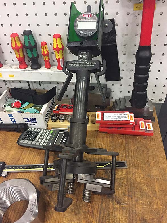
This indicator-type gage is used to measure ID threads, such as those
in large-diameter nuts for large gas turbines. Image courtesy of C. Tate.


Threads do not seem complex when simply assembling two components. However, when someone must measure threads and reproduce parts that are interchangeable with parts manufactured somewhere else in the world, threading can become the bane of one’s existence. Successful threadmaking requires proper gaging and a clear understanding of the thread requirements.

Measuring threads can be successfully performed in many ways. However, errors can create costly problems, so selecting the best measurement method is important.

Gage Selection

Selecting the proper gage requires knowing the specified thread form. Most threads conform to a standard, such as the unified thread form, ISO thread form or to an industry-specific standard like the one from the American Petroleum Institute. Threads that conform to a standard will have specific requirements for shape, size and geometric relationships that define the threads; gages will be made accordingly.


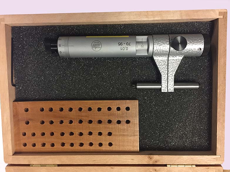
In addition to measuring ID threads, Mitsubishi Hitachi Power Systems Americas will use this set
of thread mics to develop a manufacturing process for some gas turbine hardware. Image courtesy of C. Tate.


Hard gages, like plug and ring gages, also known as GO/NO-GO gages, are the most common, especially in production environments. These gages let the user determine if the threaded element is good or bad. The two-part gages have one element that is slightly smaller than the minimum thread size and another that is slightly larger than the maximum size. When the thread is sized correctly, the GO gage will fit the threaded part but the NO-GO will not. These gages are fast, accurate and easy to use. 

Unfortunately, GO/NO-GO gages do not provide any numeric values, which can make setup and adjustment of a machine tool difficult. In cases where numeric values are needed, another type of thread gage must be used.

In terms of simplicity, GO/NO-GO systems that utilize an indicator are probably the next best thing to plug and ring gages. Like hard gages, indicator-based gages allow a user to quickly determine good from bad. However, they also provide a numerical deviation from the ideal, so the user can make necessary adjustments to the machine tool. Indicator-based gages are set with master gages, which define upper limits, lower limits or nominal thread sizes. Using upper- and lower-limit masters to set the gage is the most desirable method because it eliminates the possibility of errors.

Indicator-style gages and the masters that go with them are expensive compared to other thread gages. Fortunately, they can measure a range of sizes, which makes their cost a little more palatable. 

Indicator-style gages, like hard gages, are suitable for production environments. However, they require more training and adherence to proper setting procedures to ensure reliability.

Quantity Considerations

Toolrooms and shops that produce small quantities of parts often cannot justify the expense of indicator gages, or they simply can’t wait to have hard gages manufactured. In these situations, there are several types of micrometers, calipers and other off-the-shelf gages made specifically for thread measurement. 


The three-wire method requires the machinist to place three wires into the thread trough
so that a standard OD mic can measure across the wires. Image courtesy of C. Tate.


For OD threads, the best solution is an OD thread micrometer. OD mics can be purchased with replaceable anvils made for specific thread-pitch ranges so that one mic can correctly measure many thread pitches. OD mics with fixed anvils, on the other hand, are limited to measuring a finite range of thread pitches and appear to be headed for extinction. 

OD thread mics are sized like regular OD micrometers, such as 0" to 1" and 1" to 2", which means they can measure very small threads or large threads with equal ease and precision. 

ID threads with large diameters can also be measured with various micrometers and calipers. The most-common style resembles an inside micrometer used to measure a bored hole, except it has a thread form ground into the ends. 

For diameters less than 1", measuring ID threads with a micrometer or similar tool is all but impossible. You simply can’t place the hardware into the hole. Thread diameters less than 1" are often tapped, which does not provide any method of adjustment and negates the necessity for a gage that provides a numeric value. When thread milling small diameters, the machinist can adjust the tool data to affect thread size so a numeric value is helpful. Unfortunately, careful set up of the process and GO/NO-GO gages must suffice.


The two-part GO/NO-GO gage has one element that is slightly smaller than the minimum thread size
and another that is slightly larger than the maximum size. When the thread is sized correctly,
the GO gage will fit the threaded part but the NO-GO will not. Image courtesy of Vermont Gage.


The most basic, but arguably the most-complex, thread-measurement technique is the three-wire method. It requires the machinist to place three wires into the thread trough so that a standard OD mic can measure across the wires. A diameter is measured over the wires and a calculation determines the thread-pitch diameter. Three-wire thread measuring is the most universal method because it does not require any special tools—other than the wires—and can be used on very small and very large threads. Wires are also economical; a decent set is about $25.

While wires don’t work on ID threads, they can be used to create a set of GO/NO-GO gages in situations where there is no time or desire to purchase hard gages. Every machinist and toolmaker should own and know how to use the wires, because when all else fails, the wires will provide reliable measurements.

Thread measurement is complex, and the best practice depends on the shop and the people using the gages. Like other tools, the best way to determine what is best for your shop is to consult with the experts and test different methods. 

Having a clear definition of the thread requirements is the most important aspect of achieving acceptable results. Often it is necessary to ask the customer for input to ensure the exact requirements are obtained. If requirements seem vague or, worse, impossible to achieve, investigate the customer’s method of measurement and mimic it. While thread requirements may seem straightforward, there can be a lot of interpretation when it comes to gaging and what constitutes an acceptable thread. 

Related Glossary Terms

  • gang cutting ( milling)

    gang cutting ( milling)

    Machining with several cutters mounted on a single arbor, generally for simultaneous cutting.

  • inner diameter ( ID)

    inner diameter ( ID)

    Dimension that defines the inside diameter of a cavity or hole. See OD, outer diameter.

  • micrometer

    micrometer

    A precision instrument with a spindle moved by a finely threaded screw that is used for measuring thickness and short lengths.

  • milling

    milling

    Machining operation in which metal or other material is removed by applying power to a rotating cutter. In vertical milling, the cutting tool is mounted vertically on the spindle. In horizontal milling, the cutting tool is mounted horizontally, either directly on the spindle or on an arbor. Horizontal milling is further broken down into conventional milling, where the cutter rotates opposite the direction of feed, or “up” into the workpiece; and climb milling, where the cutter rotates in the direction of feed, or “down” into the workpiece. Milling operations include plane or surface milling, endmilling, facemilling, angle milling, form milling and profiling.

  • outer diameter ( OD)

    outer diameter ( OD)

    Dimension that defines the exterior diameter of a cylindrical or round part. See ID, inner diameter.

  • threading

    threading

    Process of both external (e.g., thread milling) and internal (e.g., tapping, thread milling) cutting, turning and rolling of threads into particular material. Standardized specifications are available to determine the desired results of the threading process. Numerous thread-series designations are written for specific applications. Threading often is performed on a lathe. Specifications such as thread height are critical in determining the strength of the threads. The material used is taken into consideration in determining the expected results of any particular application for that threaded piece. In external threading, a calculated depth is required as well as a particular angle to the cut. To perform internal threading, the exact diameter to bore the hole is critical before threading. The threads are distinguished from one another by the amount of tolerance and/or allowance that is specified. See turning.