When milling high-performance aluminum alloys,the best way to prevent part distortion is to control residual stresses.
Residual stresses in high-performance aluminum alloys pose extreme challenges to customary milling methods. In forgings or plate stock, these tensile or compressive stresses originate in deformation of the material during part fabrication and are released when the surface of the part is disturbed. Heat-treating an aluminum workpiece or machining it with endmills 1" in diameter or larger usually releases residual stresses in an uncontrolled manner. The result is part distortion.
7000-series aluminum materials such as 7050, 7055, and 7150 are particularly vulnerable to residual-stress problems. Many metalworking shops avoid jobs involving these materials because they are notorious for causing production difficulties. Other shops, however, are discovering that they can minimize part distortion by using residual-stress-management (RSM) techniques to control or reduce stress in a predictable way.
Distortion Mechanism
Although residual stresses are inherent in the work material, they may be amplified by induced stresses, such as heat and cutting forces. 7000-series aluminum is very susceptible to heat due to alloying agents in the material. If the cutter is ground improperly, or if the feed rate and speed don’t correlate, the poor shearing action in the cut will induce stress into the part. Chatter caused by cutter walk may induce stress to the point where it bows or twists the part.
Distortion of a 7000-series aluminum part during processing is caused by stresses induced by traditional manufacturing techniques. These techniques often fail to control surface core stresses that serve as a release mechanism for residual stresses in the material. Because of their over-reliance on past practices in machining aluminum, machinists may choose inappropriate processing methods to mill and heat-treat 7000-series alloys. Unless machinists use the proper machining and heat-treating techniques, they won’t be able to control the release of residual stresses in the workpiece material that lead to part distortion.
The RSM techniques discussed below apply to the milling of high-performance aluminum alloys as well as other aluminum materials (such as 2024-T3) using conventional NC machines. Although high-speed machines are being used to mill aluminum, the less sophisticated machines still are more common.
The machine tool should permit all operations to be performed on the part in the same setup. Using a versatile machine eliminates the need to move or refixture the part, thereby avoiding induced stresses due to the pressures of clamping fixtures and part handling. If a less versatile machine is used, the need for multiple setups will increase the stresses in the part. The fixture must clamp the part securely and give full support under the work. Overhang should be kept to a minimum.
On conventional NC machines, HSS, 8%-cobalt-HSS, or 10%-cobalt-HSS cutters are recommended. When a cutter less than 1" in diameter is used, controlling residual stresses isn’t a significant problem. For best results with a cutter 1" in diameter or larger, use a 3-flute endmill with a 37° helix. A 3-flute cutter has a heavier feed-rate capability than a 2-flute cutter. Although more flutes restrict chip space, they remove more chips per revolution and provide other benefits.
The recommended 37°-helix-angle cutter removes more material than a conventional 30° cutter can. The 37° angle allows the tool to remain in contact with the part at all times and helps prevent the cutter from "walking" in the cut. This provides optimum shearing action, lower cutting forces, and better chip clearance. With a helix angle larger than 37, the cutter wouldn’t have this shearing action, and chips would tend to load up.
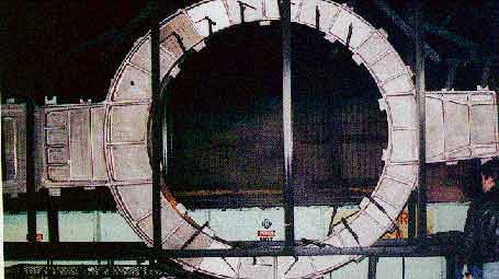
Residual-stress-management techniques were used for total control in machining this aircraft-engine support bulkhead. The 7075 aluminum part was produced to print (within 0.060" roundness and 0.030" flatness) with no distortion.
The primary relief angle should be about 8°, and the secondary clearance angle should be about 12°. This provides enough chip clearance to prevent chips from backing up. The rake angle should be ground at about 12° positive, and the dish angle should be less than 1° in order to provide stability at the bottom of the cut when plunging.
Chip slides should be intact, all the way to the tip of the cutter, to allow the material to be sheared and the chips to curl away from the tool and the part. A chip slide is the trough in the gullet of the flute where chips flow along the flute’s helical twist. Chip slides that extend all the way to the rake angle allow uninterrupted chip flow, which is a critical requirement to attain effective machining rates.
The rate of cutter wear depends primarily on cutting speed. When the rake angle along with the chip slides (the true rake angle) is positive, then cutter force and cutter temperature will decrease 10% for every degree that the rake angle increases in the positive direction. Therefore, an endmill with a larger rake angle can handle higher cutting speeds without introducing more heat (and hence more stress) into the material.
Cutting Parameters
Lower cutting speeds on conventional NC machines reduce wear at the cutting edge, prolong tool life, and minimize machine-induced stresses during the milling of 7000-series aluminum. When an HSS or cobalt-HSS cutter is used, material suppliers typically recommend a rate of 400 to 800 sfm for aluminum parts.
Once the speed is calculated, the feed rate can be determined. Running the machine at 800 sfm, for example, the machinist could maintain a feed rate of approximately 45 to 50 ipm. A direct correlation between speed and feed is needed to maintain the chipload required at lower speeds on conventional NC machines. A key consideration is the thickness of the chip taken by each tooth. To avoid tool breakage, the material-removal rate should fall between 0.025 and 0.032 ipr. When the maximum chipload value is used, a 2-flute cutter will have a chipload of 0.0125 to 0.0135 ipt, while a 3-flute cutter will have a chipload of 0.008 to 0.011 ipt.
Feed rates should be continuous and should not be reduced below the programmed rates in attempts to extend tool life or improve surface finish. Never allow the tool to dwell in the workpiece. Prolonging the cutting causes localized heat, which amplifies the residual stresses within the part. With the appropriate combination of speed and feed, a 3-flute tool with the proper geometry can last from 200% to 300% longer than a conventional 2-flute cutter.
Milling Approach
Climb milling is another practice that promotes effective RSM. Conventional milling, also known as up milling, tends to lift the workpiece from the fixture. Because the cutter rotates in the opposite direction of the feed, the opposing forces create additional stresses within the material.
In climb milling, or down milling, the work is fed in the same direction as the rotation of the cutter, and forces are directed downward. Because the workpiece is forced against the surface to which it is clamped, climb milling is suitable for machining 7000-series aluminum workpieces that are thin or hard to hold. Climb milling is more practical for machining deep, narrow slots, because the cutting action allows the tool to cut without springing under a heavy force. The cutter teeth can bite into the material with a good shearing action that helps overcome cutter forces and induced stresses.
Another consideration in selecting the milling approach is chatter. The rapid, elastic vibration that appears between the tool and the workpiece is detected by marks on the part surface. Chatter is a danger signal of possible tool chipping or fracture. Remedies include eliminating uneven motion and increasing the rigidity of the fixture. Chatter typically isn’t a problem with climb milling, because there are no opposing forces. It is less likely with low cutting forces, thick chiploads, and well-designed cutters with high rake angles and ample relief angles.
Balanced Machining
Metal-cutting operations that generate heat, and thereby add induced stresses to the residual stresses in the material, should be distributed around the part rather than performed sequentially in adjoining areas. Such nonsequential programming of operations helps control residual stresses that cause part distortion. This is the same concept autobuilders use to bolt cylinder heads to blocks. Starting at the center of the head, they tighten the bolts nonsequentially from side to side to distribute the stresses in the head and to ensure that the head is pulled down evenly against the block.
Let’s say a 7000-series aluminum workpiece requires a series of pockets to be milled. If the machinist removes material from every other pocket, it disrupts the bridges that allow stresses to move between regions of the workpiece. When the remaining pockets are machined, the distortion is reduced or nonexistent because the stresses in the adjacent pockets already have been reduced and redistributed. This allows the part to relax and minimizes part distortion. A finish cut also helps compensate for part distortion remaining after the first cut.
After heat-treatment, balanced machining operations should be applied for all material-removal processes. A "flip-flop" operation from front to rear and top to bottom, rather than from top to front to rear to bottom, will help achieve balanced machining. Flip-flop allows the part to be recentered so that equal amounts of material can be removed. Because the part is refixtured directly over previous fixturing points, the machinist has control over induced stresses.
Heat-Treatment
With RSM techniques, residual stresses in 7000-series aluminum can be controlled in machining operations prior to heat-treatment, but stresses are inevitably introduced during in-solution or in-air heat-treatment. Therefore, it’s almost always better to machine the part before heat-treatment. The complexity of most parts allows for rough milling before heat-treatment, with the final grinding operation done after heat-treatment to remove stresses.
For a part made of 7000-series aluminum, proper racking is particularly important for support during heat-treatment and quenching. Improper racking may add induced stresses to the residual stresses in the material. Annealing the part minimizes these stresses, but it is not a cure-all by itself.
Proper racking helps eliminate induced stresses that cause canning, twisting, or bowing of the part. These stresses are more of a problem in forgings than in other semifabricated parts because of forgings’ wide variety of shapes and nonuniform cross sections. For example, forged parts that are 5' to 25' long and 2' to 3' wide with heavy cross sections must be horizontally quenched. Horizontal quenching allows the thicker portion of the part to be immersed in the quenching fluid first, thereby ensuring that a large area of the part is cooled simultaneously. Vertical quenching would cool a much smaller area at one time, and the difference in temperatures between the cooled section and the heated section would promote warping. By using RSM techniques during heat-treatment and quenching, part distortion can be minimized and blueprint specifications can be readily met.
To successfully mill and heat-treat 7000-series alloys and other aluminum materials that are difficult to process, all these RSM techniques must be implemented throughout the process. With proper control of residual stresses, machinists can handle these materials easily and efficiently while optimizing part accuracy and eliminating scrap.
2-Flute vs. 3-Flute Endmills
Tools commonly used for milling 7000-series aluminum alloys include roughing, finishing, semiroughing, insert-style, and specialty cutters. These tools may have from 1 to 6 flutes and helix angles ranging from 0 to 60.
In theory, aluminum can be machined with endmills having 3 or more flutes as long as the radial depth of cut is light, no pockets are cut, and no plunge milling is done. But in practice, very few operations meet these criteria. If a machinist tries to take too heavy a cut with a 4-flute endmill, the tool could quickly turn into a "lollipop" covered with melted aluminum.
To avoid such problems when milling aluminum, machinists typically use a 2-flute endmill. It has ample room for chip evacuation and is effective for plunging and ramping. Corner radii can be easily ground on this tool.
However, a 2-flute endmill has a tendency to "walk" in the cut, because it is less rigid than endmills with more flutes and larger core diameters. In slotting operations, a 2-flute endmill often leaves one of the two walls with an inferior surface finish.
When milling aluminum, a 3-flute cutter offers significant advantages over a 2-flute cutter. With more flutes, vibrations are reduced. A 3-flute endmill has a stronger core diameter for less deflection and better cutting-edge support, providing straighter plunge milling. Because more cutting edges are in contact with the workpiece, a 3-flute tool is more rigid and less likely to "walk" in the cut. Reduced deflection also improves tool life and workpiece finish.
Until recently, standard tools with 3 or more flutes were available only with geometries intended for steel. These cutters had helix angles from 25 to 30. Because they lacked sufficient room for chip clearance, these tools generally yielded unsatisfactory results.
However, Hanita Cutting Tools Inc. has developed a 3-flute endmill with a geometry that makes aluminum easy to machine. The cutter uses a 37 helix for reduced-force cutting action and faster chip evacuation. Tool edges are specially treated to avoid chatter and provide superior surface finishes. The cutter’s rake and relief design improve edge strength and facilitate regrinding. A wide-open end-gash design speeds chip removal and makes the tool effective for plunging and ramping applications. A highly polished rake angle prevents chip adhesion.
With a 3-flute endmill, feed rates can be 50% to 70% higher than those used with a 2-flute cutter, regardless of the type of milling cut. In roughing cuts, for example, a good endmill can remove 6 cu. in. of material per horsepower. Therefore, on a 15-hp machine, the tool can remove 90 cu. in. per minute, or 1.5 cu. in. per second.
About the Author
Louis Caldarera Jr. is senior engineer scientist at McDonnell Douglas Corp., Long Beach, CA, and serves on the advisory board of Hanita Cutting Tools Inc., Mountainside, NJ.
Related Glossary Terms
- alloys
alloys
Substances having metallic properties and being composed of two or more chemical elements of which at least one is a metal.
- aluminum alloys
aluminum alloys
Aluminum containing specified quantities of alloying elements added to obtain the necessary mechanical and physical properties. Aluminum alloys are divided into two categories: wrought compositions and casting compositions. Some compositions may contain up to 10 alloying elements, but only one or two are the main alloying elements, such as copper, manganese, silicon, magnesium, zinc or tin.
- annealing
annealing
Softening a metal by heating it to and holding it at a controlled temperature, then cooling it at a controlled rate. Also performed to produce simultaneously desired changes in other properties or in the microstructure. The purposes of such changes include improvement of machinability, facilitation of cold work, improvement of mechanical or electrical properties and increase in stability of dimensions. Types of annealing include blue, black, box, bright, full, intermediate, isothermal, quench and recrystallization.
- backing
backing
1. Flexible portion of a bandsaw blade. 2. Support material behind the cutting edge of a tool. 3. Base material for coated abrasives.
- chatter
chatter
Condition of vibration involving the machine, workpiece and cutting tool. Once this condition arises, it is often self-sustaining until the problem is corrected. Chatter can be identified when lines or grooves appear at regular intervals in the workpiece. These lines or grooves are caused by the teeth of the cutter as they vibrate in and out of the workpiece and their spacing depends on the frequency of vibration.
- chip clearance
chip clearance
In milling, the groove or space provided in the cutter body that allows chips to be formed by the inserts.
- clearance
clearance
Space provided behind a tool’s land or relief to prevent rubbing and subsequent premature deterioration of the tool. See land; relief.
- climb milling ( down milling)
climb milling ( down milling)
Rotation of a milling tool in the same direction as the feed at the point of contact. Chips are cut to maximum thickness at the initial engagement of the cutter’s teeth with the workpiece and decrease in thickness at the end of engagement. See conventional milling.
- climb milling ( down milling)2
climb milling ( down milling)
Rotation of a milling tool in the same direction as the feed at the point of contact. Chips are cut to maximum thickness at the initial engagement of the cutter’s teeth with the workpiece and decrease in thickness at the end of engagement. See conventional milling.
- conventional milling ( up milling)
conventional milling ( up milling)
Cutter rotation is opposite that of the feed at the point of contact. Chips are cut at minimal thickness at the initial engagement of the cutter’s teeth with the workpiece and increase to a maximum thickness at the end of engagement. See climb milling.
- conventional milling ( up milling)2
conventional milling ( up milling)
Cutter rotation is opposite that of the feed at the point of contact. Chips are cut at minimal thickness at the initial engagement of the cutter’s teeth with the workpiece and increase to a maximum thickness at the end of engagement. See climb milling.
- cutting speed
cutting speed
Tangential velocity on the surface of the tool or workpiece at the cutting interface. The formula for cutting speed (sfm) is tool diameter 5 0.26 5 spindle speed (rpm). The formula for feed per tooth (fpt) is table feed (ipm)/number of flutes/spindle speed (rpm). The formula for spindle speed (rpm) is cutting speed (sfm) 5 3.82/tool diameter. The formula for table feed (ipm) is feed per tooth (ftp) 5 number of tool flutes 5 spindle speed (rpm).
- depth of cut
depth of cut
Distance between the bottom of the cut and the uncut surface of the workpiece, measured in a direction at right angles to the machined surface of the workpiece.
- dish
dish
Form of relief given to the face of an endmill to prevent undesirable contact with the work. Similar to clearance.
- endmill
endmill
Milling cutter held by its shank that cuts on its periphery and, if so configured, on its free end. Takes a variety of shapes (single- and double-end, roughing, ballnose and cup-end) and sizes (stub, medium, long and extra-long). Also comes with differing numbers of flutes.
- feed
feed
Rate of change of position of the tool as a whole, relative to the workpiece while cutting.
- finish cut
finish cut
Final cut made on a workpiece to generate final dimensions or specified finish. Often made using reduced feeds and higher speeds. Generally, the better the surface finish required, the longer the finish cut takes. Also, the final cut taken on an electrical-discharge-machined part.
- fixture
fixture
Device, often made in-house, that holds a specific workpiece. See jig; modular fixturing.
- flutes
flutes
Grooves and spaces in the body of a tool that permit chip removal from, and cutting-fluid application to, the point of cut.
- gang cutting ( milling)
gang cutting ( milling)
Machining with several cutters mounted on a single arbor, generally for simultaneous cutting.
- grinding
grinding
Machining operation in which material is removed from the workpiece by a powered abrasive wheel, stone, belt, paste, sheet, compound, slurry, etc. Takes various forms: surface grinding (creates flat and/or squared surfaces); cylindrical grinding (for external cylindrical and tapered shapes, fillets, undercuts, etc.); centerless grinding; chamfering; thread and form grinding; tool and cutter grinding; offhand grinding; lapping and polishing (grinding with extremely fine grits to create ultrasmooth surfaces); honing; and disc grinding.
- heat-treating
heat-treating
Process that combines controlled heating and cooling of metals or alloys in their solid state to derive desired properties. Heat-treatment can be applied to a variety of commercially used metals, including iron, steel, aluminum and copper.
- helix angle
helix angle
Angle that the tool’s leading edge makes with the plane of its centerline.
- high-speed steels ( HSS)
high-speed steels ( HSS)
Available in two major types: tungsten high-speed steels (designated by letter T having tungsten as the principal alloying element) and molybdenum high-speed steels (designated by letter M having molybdenum as the principal alloying element). The type T high-speed steels containing cobalt have higher wear resistance and greater red (hot) hardness, withstanding cutting temperature up to 1,100º F (590º C). The type T steels are used to fabricate metalcutting tools (milling cutters, drills, reamers and taps), woodworking tools, various types of punches and dies, ball and roller bearings. The type M steels are used for cutting tools and various types of dies.
- inches per minute ( ipm)
inches per minute ( ipm)
Value that refers to how far the workpiece or cutter advances linearly in 1 minute, defined as: ipm = ipt 5 number of effective teeth 5 rpm. Also known as the table feed or machine feed.
- inches per tooth ( ipt)
inches per tooth ( ipt)
Linear distance traveled by the cutter during the engagement of one tooth. Although the milling cutter is a multi-edge tool, it is the capacity of each individual cutting edge that sets the limit of the tool, defined as: ipt = ipm/number of effective teeth 5 rpm or ipt = ipr/number of effective teeth. Sometimes referred to as the chip load.
- metalcutting ( material cutting)
metalcutting ( material cutting)
Any machining process used to part metal or other material or give a workpiece a new configuration. Conventionally applies to machining operations in which a cutting tool mechanically removes material in the form of chips; applies to any process in which metal or material is removed to create new shapes. See metalforming.
- metalworking
metalworking
Any manufacturing process in which metal is processed or machined such that the workpiece is given a new shape. Broadly defined, the term includes processes such as design and layout, heat-treating, material handling and inspection.
- milling
milling
Machining operation in which metal or other material is removed by applying power to a rotating cutter. In vertical milling, the cutting tool is mounted vertically on the spindle. In horizontal milling, the cutting tool is mounted horizontally, either directly on the spindle or on an arbor. Horizontal milling is further broken down into conventional milling, where the cutter rotates opposite the direction of feed, or “up” into the workpiece; and climb milling, where the cutter rotates in the direction of feed, or “down” into the workpiece. Milling operations include plane or surface milling, endmilling, facemilling, angle milling, form milling and profiling.
- milling machine ( mill)
milling machine ( mill)
Runs endmills and arbor-mounted milling cutters. Features include a head with a spindle that drives the cutters; a column, knee and table that provide motion in the three Cartesian axes; and a base that supports the components and houses the cutting-fluid pump and reservoir. The work is mounted on the table and fed into the rotating cutter or endmill to accomplish the milling steps; vertical milling machines also feed endmills into the work by means of a spindle-mounted quill. Models range from small manual machines to big bed-type and duplex mills. All take one of three basic forms: vertical, horizontal or convertible horizontal/vertical. Vertical machines may be knee-type (the table is mounted on a knee that can be elevated) or bed-type (the table is securely supported and only moves horizontally). In general, horizontal machines are bigger and more powerful, while vertical machines are lighter but more versatile and easier to set up and operate.
- numerical control ( NC)
numerical control ( NC)
Any controlled equipment that allows an operator to program its movement by entering a series of coded numbers and symbols. See CNC, computer numerical control; DNC, direct numerical control.
- plunge milling
plunge milling
Highly productive method of metal removal in which an axial machining operation is performed in a single tool sequence. The tool makes a series of overlapping, drill-like plunges to remove part of a cylindrical plug of material one after another. Because of the increased rigidity of a Z-axis move, the tool can cover a large cross-section of material.
- quenching
quenching
Rapid cooling of the workpiece with an air, gas, liquid or solid medium. When applicable, more specific terms should be used to identify the quenching medium, the process and the cooling rate.
- rake
rake
Angle of inclination between the face of the cutting tool and the workpiece. If the face of the tool lies in a plane through the axis of the workpiece, the tool is said to have a neutral, or zero, rake. If the inclination of the tool face makes the cutting edge more acute than when the rake angle is zero, the rake is positive. If the inclination of the tool face makes the cutting edge less acute or more blunt than when the rake angle is zero, the rake is negative.
- relief
relief
Space provided behind the cutting edges to prevent rubbing. Sometimes called primary relief. Secondary relief provides additional space behind primary relief. Relief on end teeth is axial relief; relief on side teeth is peripheral relief.
- slotting
slotting
Machining, normally milling, that creates slots, grooves and similar recesses in workpieces, including T-slots and dovetails.