Parts manufacturers should head straight to their high-strength round inserts to turn nickel-base alloys.
Parts used in extreme conditions require extreme materials. The part may be a large ring or shroud in a jet engine, which operates at up to 1,200° F, or can be a down-hole component in an oil field, operating in a corrosive environment hundreds of feet underground.
So aerospace and oil and gas companies have many of their parts made from nickel-base alloys (heat-resistant superalloys). To turn these materials, which include Inconel, Hastelloy, Waspaloy and Monel, manufacturers should have their eyes firmly fixed on that humble cutting tool, the round insert.
Round inserts may be underutilized in some manufacturing sectors, but the aerospace and oil and gas industries shouldn’t be among them.
No Cutting Corners
Despite some major advantages, round inserts may be unattractive to manufacturers for several reasons. One is they can’t machine small-radius corners. For example, a 0.5 "-dia. round insert can’t turn a 90° corner with a radius of 0.004 ". Its smallest corner radius is 0.5".
The tool’s inability to create small-radius corners leads many parts manufacturers, and their programmers, to apply other insert shapes. “The CNMG is pretty much the first choice for any programmer because of the combination of flexibility and edge strength,” said Bill Tisdall, development specialist manager for toolmaker Sandvik Coromant Co., Fair Lawn, N.J. “You can OD turn, you can face, you can out-copy, you can turn to a square shoulder. With a round insert, you can’t turn to a shoulder. You can do all the other things.” (Out-copying is machine movement that combines a Z-axis movement toward the chuck with an X-axis movement away from the center line of the workpiece.)
Moreover, round inserts aren’t well suited to machining complicated profiles, like undercuts, and can’t create profiles not present in their geometry, according to Don Graham, manager of turning products for toolmaker Seco Tools Inc., Troy, Mich.
Finally, a round insert can more easily damage a workpiece than a straight-edged insert. A round insert has a relatively large radius compared with a straight-edged insert, which has small radii at its corners. A large radius means more contact surface, which results in higher cutting forces. “This can be detrimental when applied in weak setups, extended tooling or on workpiece features that have a thin cross section,” said Dale Hill, applications engineer for toolmaker Greenleaf Corp., Saegertown, Pa. Detrimental effects include workpiece deflection and vibration.
Consequently, parts manufacturers have to maximize machine tool and workholding rigidity if they want to successfully apply round inserts.
Reasons to be Round
Round inserts can be worthwhile, though, because they’re strong and can be fed at higher rates than other types of inserts, more than making up for their disadvantages in certain applications.
Time saved via higher feed rates means money saved. “The amount of money you can save [by using round inserts] over the life of running an insert is phenomenal,” Tisdall said, adding that actual cost savings depend on a shop’s overhead, annual number of components and reduction of a part number’s process time.
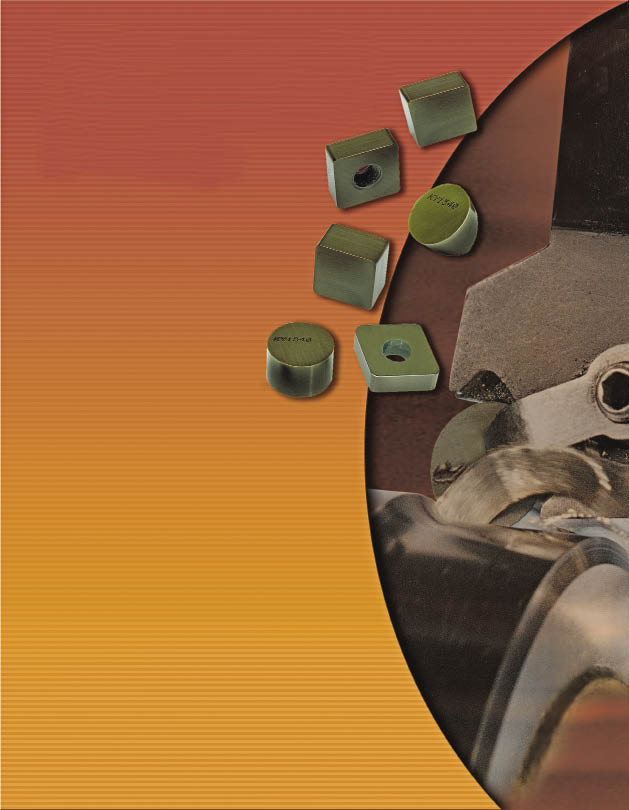
Courtesy of Kennametal
Workholders and machine tools must be rigid to apply round inserts because the tool’s radius, relatively large compared with a straight-edged insert, means more contact area and therefore more cutting pressure.
Graham estimated that round inserts can be fed 20 percent faster than other types of inserts, depending on the round tool’s chipbreaker, which can be designed for different feed rates. Graham cited a chipbreaker with a neutral land and relatively wide groove as an example, saying that a round insert can take a heavier feed rate than one with a positive rake and narrow groove width. (See recommended feeds and speeds chart on page 39.)
Round inserts can operate at higher feed rates because they have the strongest geometry. “The larger the included angle of the cutting edge, the more inherent strength you have in that insert,” said Frank Battaglia, staff engineer–global machining technology with Kennametal Inc., Latrobe, Pa.
He compared inserts’ different included angles; the 100°, 90°, 80° and 60° corners of various inserts, all the way down to a VNG-insert, which has a 35° angle. “The cross-sectional area, going from one side of that insert to the other, gets smaller and smaller as you go down in that angle,” Battaglia said. “With a round insert, it’s really just maximized to the point where you have the largest cross-sectional area going across from one side of the cutting edge to the other side.”
“There’s more material behind the force in a round insert, more material to absorb the force,” Graham added.
Their greater strength makes round inserts excellent at rough turning the scale present on forged and cast workpieces. Their strength also makes them less prone to chipping and breakage than other types of inserts.
Moreover, their strength and related long life mean round inserts are well suited to turning the large workpieces often manufactured by aerospace and oil and gas companies. “The round insert provides the best tool life and strength of any shape of an insert, so when you have a very large length of cut, you’re able to machine that full length with a round insert,” said Sandvik Coromant’s Tisdall. “With an angled insert, you’re typically going to get less tool life. You’d have to index the tool midcut.”
“Typically in aerospace, they will produce massive forgings,” Graham said. A 40 "-dia. ring that’s 0.5 " thick × 2 " wide may have started as a 48 "-dia. ring with a 6 " thickness and a 6 " width. “They remove massive amounts of material to produce that ring. That’s where a round insert is very useful because you can hog out a lot of material in an aggressive fashion,” Graham said.
Going Negative or Positive?
A parts manufacturer has to consider whether to apply a round insert with a negative geometry, a neutral one or a positive one for machining a nickel-base alloy.
According to Graham, producers of parts for oil and gas applications typically prefer negative or neutral rake angles on their round inserts because the angles provide extra strength. Those companies also like the inserts to have strong, heavy chip grooves.
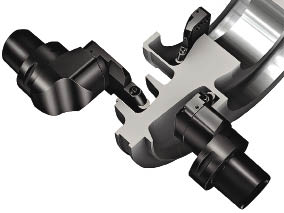
Courtesy of Sandvik Coromant
A round insert can be fed up to 20 percent faster into a workpiece than other types of inserts because the tool has the strongest geometry of any insert shape.
Greenleaf’s Hill added that a negative rake angle is particularly suitable for interrupted turning. “When it engages the workpiece, the majority of that chip or swarf impacts that top surface of the insert, which is the strongest area of that cutting tool,” he said. “So, in interrupted turning you’re now presenting the strongest area of your cutting tool to that abusive situation.”
However, a negative rake angle tends to create greater cutting force, which may not be right for a particular application. Hill recommends the correct geometry for the job. “Use negative whenever possible for strength and economy—negative tools are generally double sided, allowing for more cutting edges. Use positive geometry if surface finish, tool force or built-up edge is a concern.”
Martin Gardner, global product manager—turning, threading and grooving for toolmaker ATI Stellram, La Vergne, Tenn., agreed. He suggested an RCMT insert, which has a 7° rake angle, for this application. “That’s probably the most popular insert we see in these types of applications,” he said. “They’re used for profiling and for narrow grooves.”
He also said round inserts need an edge hone that’s not too large because that would create too much cutting force.
Recommended speeds and feeds for turning nickel-base, heat-resistant superalloys.
| Machining stage | 1st grade choice | 2nd grade choice | Cutting speed (sfm) | Feed (ipr) | DOC (in.) | Insert style | Metal-removal rate (in.3/min.) | Comments |
| First |
CC670 |
CC6065 |
500 to 656 |
0.006 to 0.008 |
Up to 0.197 |
RNG 6 |
12.20 |
Use 45° approach to reduce chip thickness and notching—first choice on good-quality forgings. |
| Intermediate |
CC6060 |
CC6065 |
656 to 984 |
0.004 to 0.008 |
0.040 to 0.118 |
RNG 4 |
7.32 |
Use round inserts wherever possible to minimize notching. |
|
CC6060 |
CC6065 |
656 to 820 |
0.004 to 0.008 |
0.040 to 0.118 |
RPGX |
4.88 |
For pocketing, use positive inserts. |
|
| Intermediate |
S05F |
GC1105 |
131 to 196 |
0.008 to 0.020 |
0.040 to 0.118 |
RCMT SM |
3.05 |
Always use an entering angle if possible to reduce notching, i.e. round RCMT. |
| Late |
S05F |
GC1105 |
131 to 196 |
0.010 to 0.020 |
0.010 to 0.020 |
RCMT SM |
— |
Profiling. |
Source: Sandvik Coromant
To Coat or Not to Coat
Besides a round insert’s geometry, part makers for aerospace and oil and gas applications must consider whether they want a coated tool.
The carbide’s structure is the first consideration. Gardner recommended a submicrograin substrate for continuous cutting without vibration. Seco Tools’ Graham agreed. “The micrograin provides increased abrasion resistance as well as deformation resistance,” he said. “The latter is extremely important when you’re machining nickel-base materials. They generate a lot of heat and pressure [when cut].” A steel, for example, softens when it gets red hot, Graham noted, whereas a superalloy retains its strength and hardness when red hot. “So even when it’s red hot, it’s still putting a lot of pressure on the insert.”
Courtesy of Greenleaf
Round inserts can be made with different features, like a chamfer (upper left and lower right) and a positive rake angle (lower right), to reduce problems that can be encountered when turning high-nickel alloys.
Also, Graham recommended the tool have a PVD coating, not a CVD coating, when machining a high-temperature alloy with a hardness of greater than 32 HRC because PVD is usually thinner and therefore better maintains a tool’s edge definition. He added that PVD coatings are also preferred because of their resistance to wear, BUE and cratering—all common failure modes when machining nickel-base alloys.
However, Graham said inserts should have CVD coatings when they’re machining softer superalloys, like Inconel 600, because the predominant failure mode is cratering and a thicker coating better protects against cratering.
Sandvik Coromant’s Tisdall generally prefers that round inserts have a CVD coating in most applications. “A CVD grade will provide better tool life and higher-speed capability because the coating is typically much thicker.” He said, however, that a CVD coating is more prone to notch wear than a PVD coating because of the CVD process itself. According to Tisdall, the CVD process creates an eta phase in an insert’s carbide matrix, depleting the matrix of its cobalt binder, which acts to resist notch wear. Also, depleting the matrix of its binder weakens the carbide substrate.
Nonetheless, Tisdall prefers a CVD coating when machining superalloys with a round insert. “The strength and chip thinning effect of a round geometry makes up for the inherent weakness of the edge line,” he said. “When machining superalloys with an insert with a point angle—CNMG, DNMG or VNMG in combination with a small lead angle tool—a PVD grade is preferable.”
“Another key issue is a coating that will adhere to the edge line for a long period of time,” Tisdall said. “What you don’t want to do is finish a large aerospace component and find out that you’ve lost size because your coating has broken down halfway through the cut. You either are going to have to do a spring pass or you might scrap a part, and you are talking about a lot of money.”
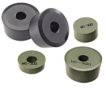
Courtesy of Sandvik Coromant
Round inserts for turning high-nickel alloys may be CVD or PVD coated depending on the tool’s performance characteristics relative to a particular alloy, such as the tool’s main failure mode.
Some aerospace companies still prefer uncoated inserts, though, because they worry about the coating contaminating parts during manufacture. “Obviously, they don’t want anything that’s going to erode or deform that structure, however minute it is,” said ATI Stellram’s Gardner. “There have been many studies about the coating diffusion into the parent material. We’ve never found that diffusion into the material with a PVD coat. That said, some manufacturers of aero engine components still like to use uncoated inserts.”
As good as they are, though, parts manufacturers may find coated, carbide round inserts insufficient for their use. “Their disadvantage is that they will be significantly limited in speed capability compared to ceramic cutting tools,” Kennametal’s Battaglia said.
He added, though, that carbide inserts are sometimes needed when a machine tool’s limitations or a part’s fixtures require running at lower speeds or during final finishing of critical aircraft components. “Often carbide is explicitly specified to be run at a low speed so that any possible damage or ‘white layer’ formation on the part surface is avoided,” Battaglia explained.
Chasing Ceramic
In a race, carbide—even a coated, submicrograin carbide—would be chasing ceramic at a long distance. “Say we take our best-case scenario of carbide—300 sfm on typical Inconel 718,” Greenleaf’s Hill said, adding that that speed involved light finishing, not roughing. “Ceramics are capable of running 800 to 900 sfm.”
Ceramics can run at such high speeds because their melting temperatures are much higher than the melting points of any metal they would cut. For example, a whisker-reinforced ceramic round insert—that is, a tool consisting of an aluminum-oxide matrix with silicon-carbide crystals—can have a melting temperature of slightly more than 2,000° C. Given such high melting points, ceramic inserts resist deformation and softening at very high temperatures.
Battaglia cautioned, though, that a ceramic round insert can still wear out if run too fast. Also, he recommended ceramic inserts’ cutting edges receive a chamfer, also known as a T-land or radius hone. He said the typical T-land has a width of 0.002 " to 0.004 " on the rake surface and an angle of 20° to 25°. “When you have a sharp-edged insert, that edge is susceptible to crack propagation,” he said. “When you add an edge preparation, you tend to direct those cutting forces more into the bulk of the material, so it makes it more difficult for a crack to propagate and lead to chipping of the cutting edge.”
According to Graham, a tool material exists for machining at even higher speeds than ceramics. “With CBN, you can run 1,000 sfm.”
A Kinder, Gentler Cut
Given their strength, it shouldn’t be surprising that round inserts need to be applied carefully to workpieces, even to high-nickel alloys.
For example, a round insert’s maximum DOC shouldn’t be more than 25 percent of the tool’s diameter. At more than 25 percent, the tool will have too much contact area with the workpiece, resulting in too much pressure and heat, Gardner said. “We’re going to just blow the insert away,” he added, “or we’re going to damage the component.”
To turn a pocket, Tisdall recommends trochoidal turning over plunging and turning to reduce potential damage to the round insert or part. In plunging and turning, an insert endures stress when plunged into a workpiece and moved across the material to turn it until it reaches where the pocket’s wall will be. The stress can lead to chipping and possibly catastrophic failure.
Trochoidal turning, however, involves smaller DOCs. “It’s a light plunge into a turn,” Tisdall said. “With a lighter DOC, you don’t have as much engagement of the insert when you come up to that wall.”
Tisdall also described a “roll-in method” of plunging and turning. A programming technique, the method includes a radius as an insert comes out of a plunge. “It’s another way of keeping the insert engaged with the workpiece without doing a sudden movement in a different direction. Let’s say you’re plunging in Z, and then you go to the X-axis and make a move in that axis. There’s a lot of stress on the insert. Here, we’re making use of a radius to basically make the process gentler on the insert.”
Courtesy of Seco Tools
Parts manufacturers can take advantage of a PCBN round tool’s ability to turn high-nickel alloys up to 1,000 sfm.
Also, a machine operator can vary a round insert’s approach angle to reduce chip thickness. “We’re always looking for thinning the chip,” Gardner said. “When we thin the chip with the approach angle, it gives us better productivity; we create less heat. The more heat we put into them, the more friction we create, the more [heat] these materials will throw back,” producing a burned-out insert. Protecting the tool from burn-out doesn’t mean applying it timidly, though.
Round inserts can’t cut small-radius corners and aren’t well suited to creating complicated profiles, but the tools have the strongest shape of any insert and can be applied at high feed rates. With appropriate rake angles and cutting strategies, the round insert is excellent at the extreme task of turning high-nickel alloys to create parts for the extreme environments inside jet engines and down-hole in oil fields. CTE
About the Author: Joseph L. Hazelton is a freelance writer with 8 years of experience writing and editing articles for metalworking publications.
Contributors
ATI Stellram
(615) 641-4200
www.stellram.com
Greenleaf Corp.
(800) 458-1850
www.greenleafcorporation.com
Kennametal Inc.
(800) 446-7738
www.kennametal.com
Sandvik Coromant Co.
(800) 726-3845
www.coromant.sandvik.com/us
Seco Tools
(800) 832-8326
www.secotools.com
Related Glossary Terms
- alloys
alloys
Substances having metallic properties and being composed of two or more chemical elements of which at least one is a metal.
- approach angle
approach angle
Angle between the insert’s side-cutting edge and the line perpendicular to the milling cutter’s axis of rotation. Approach angle, which is also known as cutting edge angle, is used with metric units of measurement. See lead angle.
- built-up edge ( BUE)
built-up edge ( BUE)
1. Permanently damaging a metal by heating to cause either incipient melting or intergranular oxidation. 2. In grinding, getting the workpiece hot enough to cause discoloration or to change the microstructure by tempering or hardening.
- built-up edge ( BUE)2
built-up edge ( BUE)
1. Permanently damaging a metal by heating to cause either incipient melting or intergranular oxidation. 2. In grinding, getting the workpiece hot enough to cause discoloration or to change the microstructure by tempering or hardening.
- ceramics
ceramics
Cutting tool materials based on aluminum oxide and silicon nitride. Ceramic tools can withstand higher cutting speeds than cemented carbide tools when machining hardened steels, cast irons and high-temperature alloys.
- chemical vapor deposition ( CVD)
chemical vapor deposition ( CVD)
High-temperature (1,000° C or higher), atmosphere-controlled process in which a chemical reaction is induced for the purpose of depositing a coating 2µm to 12µm thick on a tool’s surface. See coated tools; PVD, physical vapor deposition.
- chipbreaker
chipbreaker
Groove or other tool geometry that breaks chips into small fragments as they come off the workpiece. Designed to prevent chips from becoming so long that they are difficult to control, catch in turning parts and cause safety problems.
- chuck
chuck
Workholding device that affixes to a mill, lathe or drill-press spindle. It holds a tool or workpiece by one end, allowing it to be rotated. May also be fitted to the machine table to hold a workpiece. Two or more adjustable jaws actually hold the tool or part. May be actuated manually, pneumatically, hydraulically or electrically. See collet.
- cratering
cratering
Depressions formed on the face of a cutting tool caused by heat, pressure and the motion of chips moving across the tool’s surface.
- cubic boron nitride ( CBN)
cubic boron nitride ( CBN)
Crystal manufactured from boron nitride under high pressure and temperature. Used to cut hard-to-machine ferrous and nickel-base materials up to 70 HRC. Second hardest material after diamond. See superabrasive tools.
- cutting force
cutting force
Engagement of a tool’s cutting edge with a workpiece generates a cutting force. Such a cutting force combines tangential, feed and radial forces, which can be measured by a dynamometer. Of the three cutting force components, tangential force is the greatest. Tangential force generates torque and accounts for more than 95 percent of the machining power. See dynamometer.
- cutting speed
cutting speed
Tangential velocity on the surface of the tool or workpiece at the cutting interface. The formula for cutting speed (sfm) is tool diameter 5 0.26 5 spindle speed (rpm). The formula for feed per tooth (fpt) is table feed (ipm)/number of flutes/spindle speed (rpm). The formula for spindle speed (rpm) is cutting speed (sfm) 5 3.82/tool diameter. The formula for table feed (ipm) is feed per tooth (ftp) 5 number of tool flutes 5 spindle speed (rpm).
- diffusion
diffusion
1. Spreading of a constituent in a gas, liquid or solid, tending to make the composition of all parts uniform. 2. Spontaneous movement of atoms or molecules to new sites within a material.
- edge preparation
edge preparation
Conditioning of the cutting edge, such as a honing or chamfering, to make it stronger and less susceptible to chipping. A chamfer is a bevel on the tool’s cutting edge; the angle is measured from the cutting face downward and generally varies from 25° to 45°. Honing is the process of rounding or blunting the cutting edge with abrasives, either manually or mechanically.
- feed
feed
Rate of change of position of the tool as a whole, relative to the workpiece while cutting.
- grooving
grooving
Machining grooves and shallow channels. Example: grooving ball-bearing raceways. Typically performed by tools that are capable of light cuts at high feed rates. Imparts high-quality finish.
- hardness
hardness
Hardness is a measure of the resistance of a material to surface indentation or abrasion. There is no absolute scale for hardness. In order to express hardness quantitatively, each type of test has its own scale, which defines hardness. Indentation hardness obtained through static methods is measured by Brinell, Rockwell, Vickers and Knoop tests. Hardness without indentation is measured by a dynamic method, known as the Scleroscope test.
- included angle
included angle
Measurement of the total angle within the interior of a workpiece or the angle between any two intersecting lines or surfaces.
- land
land
Part of the tool body that remains after the flutes are cut.
- lead angle
lead angle
Angle between the side-cutting edge and the projected side of the tool shank or holder, which leads the cutting tool into the workpiece.
- metal-removal rate
metal-removal rate
Rate at which metal is removed from an unfinished part, measured in cubic inches or cubic centimeters per minute.
- metalworking
metalworking
Any manufacturing process in which metal is processed or machined such that the workpiece is given a new shape. Broadly defined, the term includes processes such as design and layout, heat-treating, material handling and inspection.
- outer diameter ( OD)
outer diameter ( OD)
Dimension that defines the exterior diameter of a cylindrical or round part. See ID, inner diameter.
- physical vapor deposition ( PVD)
physical vapor deposition ( PVD)
Tool-coating process performed at low temperature (500° C), compared to chemical vapor deposition (1,000° C). Employs electric field to generate necessary heat for depositing coating on a tool’s surface. See CVD, chemical vapor deposition.
- point angle
point angle
Included angle at the point of a twist drill or similar tool; for general-purpose tools, the point angle is typically 118°.
- polycrystalline cubic boron nitride ( PCBN)
polycrystalline cubic boron nitride ( PCBN)
Cutting tool material consisting of polycrystalline cubic boron nitride with a metallic or ceramic binder. PCBN is available either as a tip brazed to a carbide insert carrier or as a solid insert. Primarily used for cutting hardened ferrous alloys.
- profiling
profiling
Machining vertical edges of workpieces having irregular contours; normally performed with an endmill in a vertical spindle on a milling machine or with a profiler, following a pattern. See mill, milling machine.
- rake
rake
Angle of inclination between the face of the cutting tool and the workpiece. If the face of the tool lies in a plane through the axis of the workpiece, the tool is said to have a neutral, or zero, rake. If the inclination of the tool face makes the cutting edge more acute than when the rake angle is zero, the rake is positive. If the inclination of the tool face makes the cutting edge less acute or more blunt than when the rake angle is zero, the rake is negative.
- superalloys
superalloys
Tough, difficult-to-machine alloys; includes Hastelloy, Inconel and Monel. Many are nickel-base metals.
- swarf
swarf
Metal fines and grinding wheel particles generated during grinding.
- threading
threading
Process of both external (e.g., thread milling) and internal (e.g., tapping, thread milling) cutting, turning and rolling of threads into particular material. Standardized specifications are available to determine the desired results of the threading process. Numerous thread-series designations are written for specific applications. Threading often is performed on a lathe. Specifications such as thread height are critical in determining the strength of the threads. The material used is taken into consideration in determining the expected results of any particular application for that threaded piece. In external threading, a calculated depth is required as well as a particular angle to the cut. To perform internal threading, the exact diameter to bore the hole is critical before threading. The threads are distinguished from one another by the amount of tolerance and/or allowance that is specified. See turning.
- turning
turning
Workpiece is held in a chuck, mounted on a face plate or secured between centers and rotated while a cutting tool, normally a single-point tool, is fed into it along its periphery or across its end or face. Takes the form of straight turning (cutting along the periphery of the workpiece); taper turning (creating a taper); step turning (turning different-size diameters on the same work); chamfering (beveling an edge or shoulder); facing (cutting on an end); turning threads (usually external but can be internal); roughing (high-volume metal removal); and finishing (final light cuts). Performed on lathes, turning centers, chucking machines, automatic screw machines and similar machines.