Sizing Up Nickel

Author Frank Mullett
Published
September 01, 2000 - 12:00pm

Advice about endmilling nickel-based alloys.

Developments in aerospace technology have increased the use of nickel-based superalloys such as IN 100, INCO 718 and René 100. In fact, nickel-based materials account for 45 to 50 percent of the total material used in the manufacture of a gas turbine engine.

But due to their exceptional strength and corrosion resistance at high temperatures, these alloys are turning up in a widening array of applications, including rocket engines, steam powerplants, nuclear reactors, petrochemical plants and submarines. As a result, more machinists are having to contend with milling these hard-to-machine materials. Following are some basic techniques for endmilling nickel-based alloys that will lend predictability to the machining process.

A Question of Toughness

What makes a nickel-based alloy so difficult to mill? There are number of reasons, including:

  • Nickel doesn’t conduct heat very well compared to, say, steel or aluminum. This results in a higher temperature at the tool/workpiece interface, increasing the likelihood of tool tip breakage.
  • Similarly, the high cutting zone temperatures that arise when machining nickel leads to premature tool wear.
  • Though not as bad as aluminum, the formation of built-up edge when endmilling a nickel-based alloy is more noticeable than when cutting steel.
  • The high machining forces created when milling nickel causes workhardening of the part.
  • Nickel-based alloys contain refractory carbides such as chromium, titanium, tantalum, niobium, molybdenum and tungsten. These carbides appear near the grain boundaries in amounts ranging from 0.02 to 0.05 percent. This is enough to cause significant abrasive wear to the tool’s cutting edge.

Perhaps the biggest material-related variable affecting the machinability of nickel-based materials is the percentage of nickel present in the workpiece. For example, Incoloy 901 is comprised of 42.5 percent nickel. Endmills can be run twice as fast in this material than in IN 100, an alloy containing 60 percent nickel.

Solid Cuts

When it comes to the equipment component of milling nickel-based alloys, a highly rigid machine tool equipped with a shrink-fit toolholder and a stub-length endmill is the ideal setup.

One issue frequently debated is milling tool geometry. For standard cylindrical endmills, the typical starting point for a rake angle is between 0° and 5°, with a clearance angle of 8° to 12° and a flute helix angle of 30°.

Theoretically, there is an optimal tool geometry for each type of material and each set of milling conditions. But I have found that a standard cutter with a rake angle of 5°, an eccentric clearance angle of 8° and a 30° helix angle provides excellent results for most nickel-based alloys.

In addition, high-quality cutters are essential. Interrupted cutting, which can fracture and chip the tools’ cutting edges, are common failure modes when machining nickel-based materials. So to obtain consistent results, only use endmills made of the highest quality submicron-grade tungsten carbide.

In his widely read book Metal Cutting Principles, author Milton Shaw claims that “a high-cobalt-containing tungsten carbide containing relatively large amounts of TiC and tantalum carbide should be the most effective cemented carbide type for machining refractory nickel-based alloys.” This combination of materials tends to block heat from entering the tool nose, shifting the heat zone up the rake face of the tool, increasing tool life.

Unfortunately, other than cobalt content, many tool manufacturers are unwilling to reveal the detailed composition of the carbide used in their endmills. But, as a rule of thumb, a tool that has a cobalt content of 10 to 12 percent will provide a good combination of hardness and transverse rupture strength, allowing it to resist fracturing and chipping.

All endmill cutters should have a maximum flute-to-flute runout of 0.0005". This ensures that each of the flutes produces chips of the same thickness. Uneven chip thickness from flute to flute will cause premature tool failure.

The flute corners should have a small radius (0.015" to 0.030") to reduce breakage. It is also essential to have a high-quality cutting edge that has neither serrations nor microcracks.

Well Heeled

 
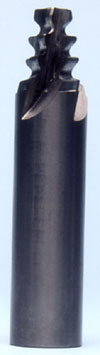
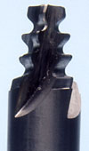
Figure 1: An important development in the milling of nickel-based materials is the use of a helix feature on endmill form cutters, like this one from Accugrind Inc.

An important development in the milling of nickel-based materials is the use of a helix feature on endmill form cutters (Figure 1). The helix limits the heavy impact experienced by each flute as it enters the material. But most of today’s form cutters lack this feature. Consequently, they are likelier to chip and fail prematurely.

The helix design distributes the tool entry forces over a broader area, reducing the impact at the edge of the flute. On form-style endmills, the helix angle must be small (10° to 15°) in order to ensure that the axial rake angle isn’t highly negative. If the axial rake angle is too high, the resultant increase in cutting force will cause premature tool wear and failure.

One general point should be noted here: When selecting roughing and finishing endmills, keep in mind that the smaller the pitch, the longer the tool life and the higher the cutting force available. The larger the pitch, the lower the cutting force.

You should check with your cutting tool supplier for precise speed and feed information for your application. Typically, though, the speed for slot milling nickel-based alloys with a carbide endmill is about 10 m/sec.

Extending Tool Life

The use of tool coatings, such as TiN, to machine nickel-based alloys has been disappointing. My experience in the aerospace industry has been that the coating tends to wear off quickly.

There is hope, though. The new multilayer coatings, such as those that incorporate alternating layers of TiN and TiCN, can extend tool life by 30 to 50 percent, depending on the application.

Surprisingly, the use of a high-pressure coolant system results in a slight decrease in tool life compared to the use of simple flood coolant. Research I conducted showed that a high-pressure coolant stream reduces the chip length along the rake face. This causes more stress on the tool nose, leading to premature tool failure.


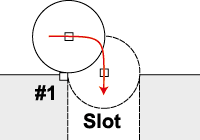
Figure 2: Using a CNC’s circular interpolation feature, the helical-form milling cutter enters the part via a circular motion that pivots about point No. 1 until the full width of the cutter engages the material. This circular entry technique allows chip thickness on the cutting edge to build gradually as the tool enters the material. Tool life increases by 50 to 70 percent over directly feeding the mill cutter into the workpiece.

However, there is a procedure that can extend the cutting life of all types of endmills in all types of materials. Called circular entry, it takes advantage of the circular interpolation feature of a CNC control (Figure 2). Circular entry can reduce the damage created when an endmill enters the workpiece material.

Upon the approach to the part, the cutter stops just before contact (0.005" to 0.010"), then begins to pivot about a cutter tangent point at one corner of the slot to be milled. This technique gradually increases the chip thickness with a climb-milling action, without lowering the feed rate. This will increase cutter life by 50 to 70 percent.

However, the technique is not as effective on endmills that contain custom forms, because the circular entry process must then use the largest diameter of the form cutter to set the pivot point. Therefore, the smaller form features on the tool may not receive the full benefit of this circular entry technique.

Utilizing this technique—along with a stable machine tool, shrink-fit toolholding and a high-quality carbide endmill—will help the growing number of machinists contend with milling hard-to-machine nickel-based alloys.

About the Author
Frank Mullett recently retired from Pratt & Whitney, East Hartford, Conn., a division of United Technologies Corp. He has nearly 40 years of machining experience.

Related Glossary Terms

  • abrasive

    abrasive

    Substance used for grinding, honing, lapping, superfinishing and polishing. Examples include garnet, emery, corundum, silicon carbide, cubic boron nitride and diamond in various grit sizes.

  • alloys

    alloys

    Substances having metallic properties and being composed of two or more chemical elements of which at least one is a metal.

  • axial rake

    axial rake

    On angular tool flutes, the angle between the tooth face and the axial plane through the tool point.

  • built-up edge ( BUE)

    built-up edge ( BUE)

    1. Permanently damaging a metal by heating to cause either incipient melting or intergranular oxidation. 2. In grinding, getting the workpiece hot enough to cause discoloration or to change the microstructure by tempering or hardening.

  • clearance

    clearance

    Space provided behind a tool’s land or relief to prevent rubbing and subsequent premature deterioration of the tool. See land; relief.

  • computer numerical control ( CNC)

    computer numerical control ( CNC)

    Microprocessor-based controller dedicated to a machine tool that permits the creation or modification of parts. Programmed numerical control activates the machine’s servos and spindle drives and controls the various machining operations. See DNC, direct numerical control; NC, numerical control.

  • coolant

    coolant

    Fluid that reduces temperature buildup at the tool/workpiece interface during machining. Normally takes the form of a liquid such as soluble or chemical mixtures (semisynthetic, synthetic) but can be pressurized air or other gas. Because of water’s ability to absorb great quantities of heat, it is widely used as a coolant and vehicle for various cutting compounds, with the water-to-compound ratio varying with the machining task. See cutting fluid; semisynthetic cutting fluid; soluble-oil cutting fluid; synthetic cutting fluid.

  • corrosion resistance

    corrosion resistance

    Ability of an alloy or material to withstand rust and corrosion. These are properties fostered by nickel and chromium in alloys such as stainless steel.

  • cutting force

    cutting force

    Engagement of a tool’s cutting edge with a workpiece generates a cutting force. Such a cutting force combines tangential, feed and radial forces, which can be measured by a dynamometer. Of the three cutting force components, tangential force is the greatest. Tangential force generates torque and accounts for more than 95 percent of the machining power. See dynamometer.

  • endmill

    endmill

    Milling cutter held by its shank that cuts on its periphery and, if so configured, on its free end. Takes a variety of shapes (single- and double-end, roughing, ballnose and cup-end) and sizes (stub, medium, long and extra-long). Also comes with differing numbers of flutes.

  • endmilling

    endmilling

    Operation in which the cutter is mounted on the machine’s spindle rather than on an arbor. Commonly associated with facing operations on a milling machine.

  • feed

    feed

    Rate of change of position of the tool as a whole, relative to the workpiece while cutting.

  • flutes

    flutes

    Grooves and spaces in the body of a tool that permit chip removal from, and cutting-fluid application to, the point of cut.

  • form cutter

    form cutter

    Cutter shaped to cut stepped, angular or irregular forms in the workpiece. The cutting-edge contour corresponds to the workpiece shape required. The cutter can often be reground repeatedly without changing the cutting-edge shape. Two general classes: straight and circular.

  • gang cutting ( milling)

    gang cutting ( milling)

    Machining with several cutters mounted on a single arbor, generally for simultaneous cutting.

  • hardness

    hardness

    Hardness is a measure of the resistance of a material to surface indentation or abrasion. There is no absolute scale for hardness. In order to express hardness quantitatively, each type of test has its own scale, which defines hardness. Indentation hardness obtained through static methods is measured by Brinell, Rockwell, Vickers and Knoop tests. Hardness without indentation is measured by a dynamic method, known as the Scleroscope test.

  • helix angle

    helix angle

    Angle that the tool’s leading edge makes with the plane of its centerline.

  • interpolation

    interpolation

    Process of generating a sufficient number of positioning commands for the servomotors driving the machine tool so the path of the tool closely approximates the ideal path. See CNC, computer numerical control; NC, numerical control.

  • machinability

    machinability

    The relative ease of machining metals and alloys.

  • milling

    milling

    Machining operation in which metal or other material is removed by applying power to a rotating cutter. In vertical milling, the cutting tool is mounted vertically on the spindle. In horizontal milling, the cutting tool is mounted horizontally, either directly on the spindle or on an arbor. Horizontal milling is further broken down into conventional milling, where the cutter rotates opposite the direction of feed, or “up” into the workpiece; and climb milling, where the cutter rotates in the direction of feed, or “down” into the workpiece. Milling operations include plane or surface milling, endmilling, facemilling, angle milling, form milling and profiling.

  • milling cutter

    milling cutter

    Loosely, any milling tool. Horizontal cutters take the form of plain milling cutters, plain spiral-tooth cutters, helical cutters, side-milling cutters, staggered-tooth side-milling cutters, facemilling cutters, angular cutters, double-angle cutters, convex and concave form-milling cutters, straddle-sprocket cutters, spur-gear cutters, corner-rounding cutters and slitting saws. Vertical cutters use shank-mounted cutting tools, including endmills, T-slot cutters, Woodruff keyseat cutters and dovetail cutters; these may also be used on horizontal mills. See milling.

  • milling machine ( mill)

    milling machine ( mill)

    Runs endmills and arbor-mounted milling cutters. Features include a head with a spindle that drives the cutters; a column, knee and table that provide motion in the three Cartesian axes; and a base that supports the components and houses the cutting-fluid pump and reservoir. The work is mounted on the table and fed into the rotating cutter or endmill to accomplish the milling steps; vertical milling machines also feed endmills into the work by means of a spindle-mounted quill. Models range from small manual machines to big bed-type and duplex mills. All take one of three basic forms: vertical, horizontal or convertible horizontal/vertical. Vertical machines may be knee-type (the table is mounted on a knee that can be elevated) or bed-type (the table is securely supported and only moves horizontally). In general, horizontal machines are bigger and more powerful, while vertical machines are lighter but more versatile and easier to set up and operate.

  • pitch

    pitch

    1. On a saw blade, the number of teeth per inch. 2. In threading, the number of threads per inch.

  • rake

    rake

    Angle of inclination between the face of the cutting tool and the workpiece. If the face of the tool lies in a plane through the axis of the workpiece, the tool is said to have a neutral, or zero, rake. If the inclination of the tool face makes the cutting edge more acute than when the rake angle is zero, the rake is positive. If the inclination of the tool face makes the cutting edge less acute or more blunt than when the rake angle is zero, the rake is negative.

  • shrink-fit toolholding

    shrink-fit toolholding

    Method of holding a round-shank cutting tool in a toolholder. To shrink-fit, the toolholder is heated in order to expand its bore, allowing a tool to be inserted. As the holder cools, the bore contracts around the shank to firmly hold the tool in place.

  • superalloys

    superalloys

    Tough, difficult-to-machine alloys; includes Hastelloy, Inconel and Monel. Many are nickel-base metals.

  • titanium carbide ( TiC)

    titanium carbide ( TiC)

    Extremely hard material added to tungsten carbide to reduce cratering and built-up edge. Also used as a tool coating. See coated tools.

  • titanium carbonitride ( TiCN)

    titanium carbonitride ( TiCN)

    Often used as a tool coating. See coated tools.

  • titanium nitride ( TiN)

    titanium nitride ( TiN)

    Added to titanium-carbide tooling to permit machining of hard metals at high speeds. Also used as a tool coating. See coated tools.

  • toolholder

    toolholder

    Secures a cutting tool during a machining operation. Basic types include block, cartridge, chuck, collet, fixed, modular, quick-change and rotating.

  • tungsten carbide ( WC)

    tungsten carbide ( WC)

    Intermetallic compound consisting of equal parts, by atomic weight, of tungsten and carbon. Sometimes tungsten carbide is used in reference to the cemented tungsten carbide material with cobalt added and/or with titanium carbide or tantalum carbide added. Thus, the tungsten carbide may be used to refer to pure tungsten carbide as well as co-bonded tungsten carbide, which may or may not contain added titanium carbide and/or tantalum carbide.

  • turning

    turning

    Workpiece is held in a chuck, mounted on a face plate or secured between centers and rotated while a cutting tool, normally a single-point tool, is fed into it along its periphery or across its end or face. Takes the form of straight turning (cutting along the periphery of the workpiece); taper turning (creating a taper); step turning (turning different-size diameters on the same work); chamfering (beveling an edge or shoulder); facing (cutting on an end); turning threads (usually external but can be internal); roughing (high-volume metal removal); and finishing (final light cuts). Performed on lathes, turning centers, chucking machines, automatic screw machines and similar machines.

  • workhardening

    workhardening

    Tendency of all metals to become harder when they are machined or subjected to other stresses and strains. This trait is particularly pronounced in soft, low-carbon steel or alloys containing nickel and manganese—nonmagnetic stainless steel, high-manganese steel and the superalloys Inconel and Monel.

Author

Frank Mullett retired from Pratt & Whitney, East Hartford, Conn., a division of United Technologies Corp. He has nearly 40 years of machining experience.