In the finest Yankee tradition, American job shops develop creative tooling and workholding solutions to keep the wheels of industry turning and get work out the door when the need arises. There is one such operation that is common enough—and tricky enough if not handled properly—that most experienced machinists have at least one exciting story to tell.
Most folks who run an engine lathe often work on the ends of long shafts, or rods, that protrude unsupported out of the headstock. Depending on the shaft diameter and how much unsupported length sticks out, this operation can be dangerous because of the high potential for shaft whip. However, with the proper tooling, this operation is a cinch to perform safely.
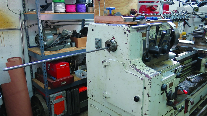
An unsupported shaft protruding from the headstock can be dangerous. Images courtesy of T. Lipton.
As the unsupported, protruding shaft rotates, it tends to oscillate. Unchecked, the shaft can start to whip. As the speed increases, this whipping can become self-reinforcing and cause the shaft to bend, destroying anything in its path as it spins like a windmill.
Best practice is to have no part of a shaft protruding unsupported from the headstock. However, this is not always possible, because job shops are called on to make whatever custom parts stumble through the door. Fortunately, there are good ways to greatly reduce—or even eliminate—the risk.
For small, quick jobs, insert a cork that’s bored to fit the workpiece diameter into the open spindle bore to support the shaft as it exits the headstock. This cheap and easy solution is for shafts that slightly protrude from the headstock. It’s a simple idea for supporting shafts smaller than the ID of the spindle on the center of rotation.
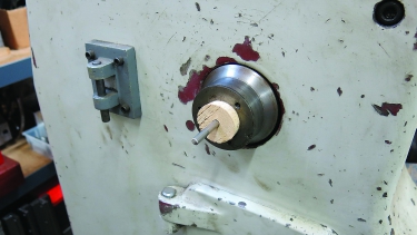
Inserting a cork in the spindle bore is one way to work with slightly protruding shafts.
Another useful support accessory is a small chuck, which can be adapted to fit the rear of the headstock. This approach is suitable for a range of diameters, and you can accurately center the chuck to the spindle’s rotational axis. This detail is important for deep-hole drilling in the ends of a shaft or for features that need to be very accurately machined, relative to the shaft axis.
The further the workpiece extends from the headstock, the more important it is to support and control the free end of the shaft. Typically, these scary, long-shaft operations are performed at low cutting speeds to reduce the risk of whip, which tends to produce poor surface finishes while increasing machining time.
To securely support long shafts, mount a small steady rest on a stand behind the headstock. I use a small steady rest from my Monarch 10EE lathe because its fingers close to a small diameter. I also added crowned roller cam followers to the tips of the fingers to minimize workpiece marks.
The steady-rest support stand must be aligned accurately with the lathe spindle. I suggest mounting the stand slightly below the machine’s theoretical centerline. This allows you to easily shim up the stand to bring it into accurate alignment with the spindle. If the stand is even a bit too high, you face heartache aligning the shaft on the center of rotation. Allow for a little wiggle room on the stand’s mounting anchors so you can make fine adjustments.
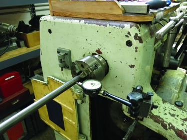
A small chuck can be adapted to fit the rear of the headstock.
This steady rest on a stand supports the extended shaft directly, with the steady rest tracking on the shaft surface. This is fine for large, one-off shafts. The steady rest supports the end of the shaft that protrudes from the headstock and keeps it accurately on center. You can then rotate the shaft at the proper cutting speed for the application and material type.
In addition, for either long runs of parts or really small shafts, it may make more sense to place a tube between the rear handy-dandy headstock chuck and the steady rest. This behaves like a proper spindle liner and allows you to swap out a shaft quickly by withdrawing the finished shaft from the tube and inserting another one.
Invest in tooling that reduces setup time. It will pay you back a thousand times over.
Related Glossary Terms
- chuck
chuck
Workholding device that affixes to a mill, lathe or drill-press spindle. It holds a tool or workpiece by one end, allowing it to be rotated. May also be fitted to the machine table to hold a workpiece. Two or more adjustable jaws actually hold the tool or part. May be actuated manually, pneumatically, hydraulically or electrically. See collet.
- computer-aided manufacturing ( CAM)
computer-aided manufacturing ( CAM)
Use of computers to control machining and manufacturing processes.
- cutting speed
cutting speed
Tangential velocity on the surface of the tool or workpiece at the cutting interface. The formula for cutting speed (sfm) is tool diameter 5 0.26 5 spindle speed (rpm). The formula for feed per tooth (fpt) is table feed (ipm)/number of flutes/spindle speed (rpm). The formula for spindle speed (rpm) is cutting speed (sfm) 5 3.82/tool diameter. The formula for table feed (ipm) is feed per tooth (ftp) 5 number of tool flutes 5 spindle speed (rpm).
- inner diameter ( ID)
inner diameter ( ID)
Dimension that defines the inside diameter of a cavity or hole. See OD, outer diameter.
- lathe
lathe
Turning machine capable of sawing, milling, grinding, gear-cutting, drilling, reaming, boring, threading, facing, chamfering, grooving, knurling, spinning, parting, necking, taper-cutting, and cam- and eccentric-cutting, as well as step- and straight-turning. Comes in a variety of forms, ranging from manual to semiautomatic to fully automatic, with major types being engine lathes, turning and contouring lathes, turret lathes and numerical-control lathes. The engine lathe consists of a headstock and spindle, tailstock, bed, carriage (complete with apron) and cross slides. Features include gear- (speed) and feed-selector levers, toolpost, compound rest, lead screw and reversing lead screw, threading dial and rapid-traverse lever. Special lathe types include through-the-spindle, camshaft and crankshaft, brake drum and rotor, spinning and gun-barrel machines. Toolroom and bench lathes are used for precision work; the former for tool-and-die work and similar tasks, the latter for small workpieces (instruments, watches), normally without a power feed. Models are typically designated according to their “swing,” or the largest-diameter workpiece that can be rotated; bed length, or the distance between centers; and horsepower generated. See turning machine.
- steady rest
steady rest
Supports long, thin or flexible work being turned on a lathe. Mounts on the bed’s ways and, unlike a follower rest, remains at the point where mounted. See follower rest.
- turning
turning
Workpiece is held in a chuck, mounted on a face plate or secured between centers and rotated while a cutting tool, normally a single-point tool, is fed into it along its periphery or across its end or face. Takes the form of straight turning (cutting along the periphery of the workpiece); taper turning (creating a taper); step turning (turning different-size diameters on the same work); chamfering (beveling an edge or shoulder); facing (cutting on an end); turning threads (usually external but can be internal); roughing (high-volume metal removal); and finishing (final light cuts). Performed on lathes, turning centers, chucking machines, automatic screw machines and similar machines.
Author

Tom Lipton is a career metalworker from the San Francisco Bay area who has worked at various job shops. For more information, visit his blog and YouTube video channel.