Part distortion is a major cost factor in the production of metallic parts, especially in the case of large and thin-walled workpieces that play an important role in lightweight design or in aerospace.
Along with partners, Fraunhofer Institute for Production Technology in Aachen, Germany, has developed a system for reducing part distortion caused by residual stresses. With a model-based process design and a new type of clamping system, companies will be able to significantly reduce part distortion when milling in the future.
During production and subsequent heat treatment of metallic blanks, residual stresses are generated, which lead to shape and dimensional deviations of workpieces while machining. Particularly after unclamping, when a workpiece is released from the clamping system, substantial distortion of the part occurs. Part distortion of this kind means that the manufacturing tolerances cannot be maintained and the part has to be reworked.
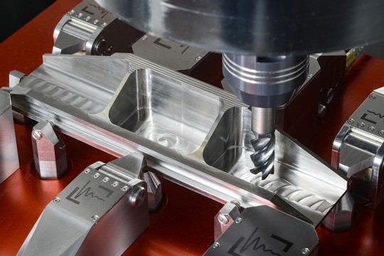
A team from Fraunhofer IPT, together with partners in the VoKoES research project, developed a concept consisting of simulation software and a new type of clamping system that can be used to predict and reduce part distortion during milling of rolled and heat-treated workpieces. Using the example of an aerospace structural component made of the titanium alloy Ti6AI4V, the team was able to demonstrate that the solutions reduced distortion by 94%.
To this end, the researchers and their partner Access e.V. first programmed a thermomechanical finite element method simulation to determine residual stress states in heat-treated blanks. In addition, a numerical distortion simulation was developed that predicts part distortion after each milling operation. Fraunhofer IPT researchers programmed the simulation with the Institute of Structural Mechanics and Lightweight Design at RWTH Aachen University based on the finite cell method.
With project partner ModuleWorks GmbH, Fraunhofer’s team integrated the simulation software into a CAM system for toolpath planning. Based on the part distortion prediction, the team tested various compensation methods, such as varying the machining sequence or the position of the target part in the blank. The results of the compensation methods are visualized directly in the CAM system. The integration into the CAM system has the benefit that no additional software is required. Another advantage of the process is that it basically can be applied to all workpiece geometries, as well as subtractive manufacturing processes. CTE
— Fraunhofer Institute for Production Technology
Related Glossary Terms
- computer-aided manufacturing ( CAM)
computer-aided manufacturing ( CAM)
Use of computers to control machining and manufacturing processes.
- gang cutting ( milling)
gang cutting ( milling)
Machining with several cutters mounted on a single arbor, generally for simultaneous cutting.
- inches per tooth ( ipt)
inches per tooth ( ipt)
Linear distance traveled by the cutter during the engagement of one tooth. Although the milling cutter is a multi-edge tool, it is the capacity of each individual cutting edge that sets the limit of the tool, defined as: ipt = ipm/number of effective teeth 5 rpm or ipt = ipr/number of effective teeth. Sometimes referred to as the chip load.
- milling
milling
Machining operation in which metal or other material is removed by applying power to a rotating cutter. In vertical milling, the cutting tool is mounted vertically on the spindle. In horizontal milling, the cutting tool is mounted horizontally, either directly on the spindle or on an arbor. Horizontal milling is further broken down into conventional milling, where the cutter rotates opposite the direction of feed, or “up” into the workpiece; and climb milling, where the cutter rotates in the direction of feed, or “down” into the workpiece. Milling operations include plane or surface milling, endmilling, facemilling, angle milling, form milling and profiling.
- residual stress
residual stress
Stress present in a body that is free of external forces or thermal gradients.
- toolpath( cutter path)
toolpath( cutter path)
2-D or 3-D path generated by program code or a CAM system and followed by tool when machining a part.
