A typical CNC lathe program is quite short compared to some of the mammoth CAM-generated programs for milling machines. Here are some tips and tricks to programming a CNC lathe.
All images courtesy T. Lipton
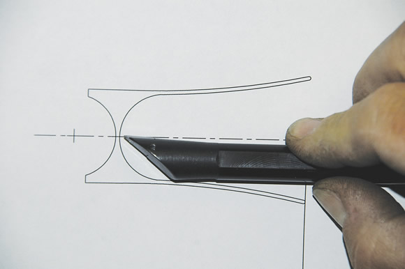
Use a full-scale drawing to check tool clearances with the actual tools you plan on applying.
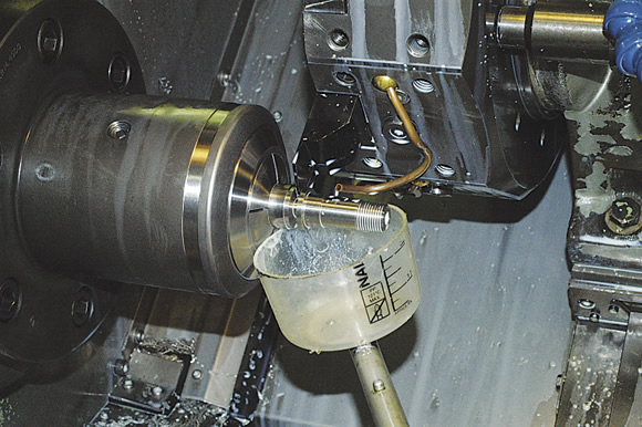
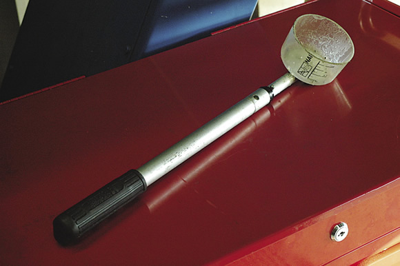
If you don’t have a parts catcher on your lathe, catch parts with a catch cup, such as this one with a telescoping handle.
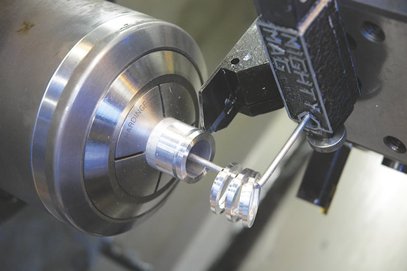
Delicate parts that you don’t want going through the chip conveyor can be caught using a magnetic catcher snapped onto the parting station.
- Because I operate lathes without CAM software, I have set up my program library into families of parts. I use a couple of generic starting templates to get the machine into a basic configuration, then start adding program elements and events.
- Using multiple windows in the text editor, I can copy and paste from one program window to the next. Once you have an inventory of working, tested programs in a few different workpiece materials, it becomes easier to leverage this work against another job. In the low-volume job shop world, anything to speed up the non-part-making portion of a process is worth trying.
- Copious notes within the program help speed up the identification of specific elements that you may want to reuse in another program. This is a good thing to do during the lag time while running parts. You can develop several generic program scenarios that frequently repeat and just need some quick editing to run.
- Use a full-scale drawing to check tool clearances with the actual tools you plan on applying. When in doubt, check it out. The bottom of a deep bore is not the place to find out the tool didn’t have enough clearance.
- In many cases, it’s nice to have parts come off a lathe complete. However, this is not always possible or practical. One useful trick is to cut multiple diameters and recesses into soft jaws so you can flip a part after a pause and finish a part in one cycle. There’s nothing like having a machine set up to run complete parts when the customer calls and increases the quantity. Programming and setting up to complete parts in one fixturing allows you to leverage the initial setup and reduce setup time on repeat jobs.
- It’s nice to complete a part from one side of the workpiece. One thing that prevents doing this easily is the final little chamfer or edge break on the ID of a bore that you are parting off into. You can use a threading tool modified to 45° to prechamfer the ID where the parting tool will break through. You can also profile the chamfer with a standard internal grooving tool. If you choose that route, be sure to pregroove straight in a few thousandths of an inch deeper than the chamfer before profiling with a regular grooving tool. It can completely eliminate a secondary operation and the associated handling and price of an extra tool change.
- Delicate parts that shouldn’t go through the chip conveyor can be caught using a magnetic catcher snapped onto the parting station. Be sure to include an M01 or M00 full stop in the program to remove the parts before too many collect and cause a problem.
- If you don’t have a parts catcher on your lathe, use constant cutting speed when parting right up to the point where the piece almost detaches, then switch to a slower constant speed for the final parting off. This prevents flinging the part against the turret or enclosure and damaging it.
- If you really need to catch the part, use an M01 or M00 right before the part separates and use a catch cup on a stick—the one I made has a telescoping handle (see photo on page 23). Be sure to turn the coolant off in the program so you don’t take a bath when you fire it back up, but don’t leave too much to part off with the coolant turned off. Leave just enough to give you time to sneak your catch cup into position.
- Keep a simple, easy-to-edit program in the control for boring soft jaws or any other repetitive operation your shop encounters. This is a common setup event for a CNC lathe. If your control supports parametric programming, so much the better. A soft jaw program might be as simple as changing a couple of values at the beginning of the program and touching off the Z-axis. CTE
About the Author: Tom Lipton is a career metalworker who has worked at various job shops that produce parts for the consumer product development, laboratory equipment, medical services and custom machinery design industries. He has received six U.S. patents and lives in Alamo, Calif. For more information, visit his blog at oxtool.blogspot.com and video channel at www.youtube.com/user/oxtoolco. Lipton’s column is adapted from information in his book “Metalworking Sink or Swim: Tips and Tricks for Machinists, Welders, and Fabricators,” published by Industrial Press Inc., South Norwalk, Conn. The publisher can be reached by calling (888) 528-7852 or visiting www.industrialpress.com. By indicating the code CTE-2014 when ordering, CTE readers will receive a 20 percent discount off the book’s list price of $44.95.
Related Glossary Terms
- boring
boring
Enlarging a hole that already has been drilled or cored. Generally, it is an operation of truing the previously drilled hole with a single-point, lathe-type tool. Boring is essentially internal turning, in that usually a single-point cutting tool forms the internal shape. Some tools are available with two cutting edges to balance cutting forces.
- clearance
clearance
Space provided behind a tool’s land or relief to prevent rubbing and subsequent premature deterioration of the tool. See land; relief.
- computer numerical control ( CNC)
computer numerical control ( CNC)
Microprocessor-based controller dedicated to a machine tool that permits the creation or modification of parts. Programmed numerical control activates the machine’s servos and spindle drives and controls the various machining operations. See DNC, direct numerical control; NC, numerical control.
- computer-aided manufacturing ( CAM)
computer-aided manufacturing ( CAM)
Use of computers to control machining and manufacturing processes.
- coolant
coolant
Fluid that reduces temperature buildup at the tool/workpiece interface during machining. Normally takes the form of a liquid such as soluble or chemical mixtures (semisynthetic, synthetic) but can be pressurized air or other gas. Because of water’s ability to absorb great quantities of heat, it is widely used as a coolant and vehicle for various cutting compounds, with the water-to-compound ratio varying with the machining task. See cutting fluid; semisynthetic cutting fluid; soluble-oil cutting fluid; synthetic cutting fluid.
- cutting speed
cutting speed
Tangential velocity on the surface of the tool or workpiece at the cutting interface. The formula for cutting speed (sfm) is tool diameter 5 0.26 5 spindle speed (rpm). The formula for feed per tooth (fpt) is table feed (ipm)/number of flutes/spindle speed (rpm). The formula for spindle speed (rpm) is cutting speed (sfm) 5 3.82/tool diameter. The formula for table feed (ipm) is feed per tooth (ftp) 5 number of tool flutes 5 spindle speed (rpm).
- gang cutting ( milling)
gang cutting ( milling)
Machining with several cutters mounted on a single arbor, generally for simultaneous cutting.
- grooving
grooving
Machining grooves and shallow channels. Example: grooving ball-bearing raceways. Typically performed by tools that are capable of light cuts at high feed rates. Imparts high-quality finish.
- inner diameter ( ID)
inner diameter ( ID)
Dimension that defines the inside diameter of a cavity or hole. See OD, outer diameter.
- lathe
lathe
Turning machine capable of sawing, milling, grinding, gear-cutting, drilling, reaming, boring, threading, facing, chamfering, grooving, knurling, spinning, parting, necking, taper-cutting, and cam- and eccentric-cutting, as well as step- and straight-turning. Comes in a variety of forms, ranging from manual to semiautomatic to fully automatic, with major types being engine lathes, turning and contouring lathes, turret lathes and numerical-control lathes. The engine lathe consists of a headstock and spindle, tailstock, bed, carriage (complete with apron) and cross slides. Features include gear- (speed) and feed-selector levers, toolpost, compound rest, lead screw and reversing lead screw, threading dial and rapid-traverse lever. Special lathe types include through-the-spindle, camshaft and crankshaft, brake drum and rotor, spinning and gun-barrel machines. Toolroom and bench lathes are used for precision work; the former for tool-and-die work and similar tasks, the latter for small workpieces (instruments, watches), normally without a power feed. Models are typically designated according to their “swing,” or the largest-diameter workpiece that can be rotated; bed length, or the distance between centers; and horsepower generated. See turning machine.
- milling
milling
Machining operation in which metal or other material is removed by applying power to a rotating cutter. In vertical milling, the cutting tool is mounted vertically on the spindle. In horizontal milling, the cutting tool is mounted horizontally, either directly on the spindle or on an arbor. Horizontal milling is further broken down into conventional milling, where the cutter rotates opposite the direction of feed, or “up” into the workpiece; and climb milling, where the cutter rotates in the direction of feed, or “down” into the workpiece. Milling operations include plane or surface milling, endmilling, facemilling, angle milling, form milling and profiling.
- parting
parting
When used in lathe or screw-machine operations, this process separates a completed part from chuck-held or collet-fed stock by means of a very narrow, flat-end cutting, or parting, tool.
- profiling
profiling
Machining vertical edges of workpieces having irregular contours; normally performed with an endmill in a vertical spindle on a milling machine or with a profiler, following a pattern. See mill, milling machine.
- threading
threading
Process of both external (e.g., thread milling) and internal (e.g., tapping, thread milling) cutting, turning and rolling of threads into particular material. Standardized specifications are available to determine the desired results of the threading process. Numerous thread-series designations are written for specific applications. Threading often is performed on a lathe. Specifications such as thread height are critical in determining the strength of the threads. The material used is taken into consideration in determining the expected results of any particular application for that threaded piece. In external threading, a calculated depth is required as well as a particular angle to the cut. To perform internal threading, the exact diameter to bore the hole is critical before threading. The threads are distinguished from one another by the amount of tolerance and/or allowance that is specified. See turning.
Author

Tom Lipton is a career metalworker from the San Francisco Bay area who has worked at various job shops. For more information, visit his blog and YouTube video channel.