Courtesy of All photos: D. Nelson
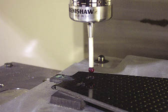
Spindle probe in position to check the surface of a chamfered hole.
While some may question its use, on-machine probing can reduce setup time while boosting in-process dimension control and enabling part verification.
The benefits of using probes on machine tools are not always obvious. Objections such as: “it adds cycle time” and “machine tools should cut, not measure” are common.
However, all shops want to boost productivity and minimize costs. On-machine probing can help accomplish these goals through setup-time reduction, in-process control of critical dimensions and part verification.
On-machine probing systems typically include two probes. A tool setter probe measures the length and diameter of tools while a spindle probe locates part fixtures, workpieces or both. Probes work in conjunction with a machine’s servo encoders and control system to effectively turn the machine tool into a measuring device that automates the process of making offsets.
Tool Protection
Machine shops typically use on-machine probing for several reasons. For example, when Rosene Machine Inc. bought its first horizontal machining center, a Makino a51 equipped with a pallet changer, it also wanted protection against broken tools. “The machine runs longer with less operator intervention than other machines,” said Dennis Rosene, president of the Firth, Neb., job shop. “We wanted some protection against the cascading effect of broken tools. We knew that probing would add a little cycle time, but in the long run it saved money by extending tool life and preventing scrap parts.”
Rosene purchased a Renishaw TS27R tool setter probe, but initially saw no reason to buy a spindle probe to accompany it until a serviceman installed one so the shop could try it. “We quickly figured out just how much help the spindle probe was,” Rosene said. “It made setups far easier since it wasn’t easy to reach in the machine to manually dial in fixtures from one side.”
As a result, the shop had to rethink what tool length offsets should look like. The shop was used to seeing negative numbers for tool lengths in its offset page. When the probe measured tools, it found the actual tool lengths and input them as positive values.
When tools are touched off manually, the tool length offset is a relationship of the tool to the workpiece. Each tool has an offset that represents where the tool touches the part relative to the machine coordinates.
Probing assigns a unique value to a tool assembly. The tool remains independent of the workpiece location and the tool’s offset can stay with the tool, thus eliminating the need to touch off the tool for every setup of a new part run.
Manual setups typically involve touching the tool tips on the top of a workpiece. Manually jogging the tool into a near-collision situation is risky, at best, particularly for delicate tools such as small-diameter drills. Tools can chip or break during this process.
Even a conscientious operator can make mistakes. Whenever manually entering numbers is required, mistakes such as transposing digits or forgetting a decimal point can easily be made and repeated with drastic effects.
Most CNC machining errors do not happen in-process. They occur during setup—the most common manual operation—in subsequent tool changes and during workpiece transfers. If these operations are partially automated, the possibility of error is reduced dramatically.
That was the case at Rosene Machine. The advantages of using a spindle probe became even more evident as the shop searched for ways to reduce machining costs. On one part, the shop cut machining costs by nearly 50 percent, based partly on its ability to dial in every part loaded in the machine as part of the machining process.
Finding the Workpiece
Using probing as part of an automatic process to find a workpiece within the machine envelope also offers the potential of machining parts in ways not normally thought to be profitable.
Because the machine can locate the workpiece, it can compensate for problems that may exist with locating parts consistently in fixtures. For example, many workpieces have size variations that limit machining options. If a casting has part variations that are within 1⁄32 ", it will be impossible to machine true-positioning tolerances of ±0.005 " without some means of setting the work offsets after loading each workpiece into the fixture.
On-machine spindle probes can check each workpiece prior to machining and reset the work offset. While using a probe in-process adds to the cycle time, it offers several advantages.
Rosene Machine saw the advantage of using the spindle probe after setting up the first production run on its new HMC. As previously mentioned, reaching into a horizontal machine to dial in fixtures is difficult for the operator. The problem comes from having only one place of entry, with climbing into the work envelope as the only means to see the workpiece and reach dial indicators and edge finders. This problem can occur on vertical machines, too.
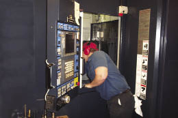
Jon Alexander of Rosene Machine demonstrates the difficulty of reaching into a horizontal machining center.
Workpieces that are near-net shape make properly locating the workpiece more critical. In the case of Rosene Machine’s first production run on the HMC, the shop had material laser cut by a local shop. The laser cut a critical area, leaving only enough material for a finish pass, thus eliminating the roughing passes present in its previous manufacturing strategy.
Near-net-shape workpieces are typically rough and have drafted edges that offer fixturing challenges. Holding each workpiece in exactly the same location is difficult, making fixtures more expensive and prep work necessary. However, spindle probes offer the option of automatically locating work offsets.
Locationally Challenged
Of course, locating a part feature can be a problem with other types of workpieces as well. For example, molded or cast metal workpieces can present locating challenges, as can molded composite parts.
Royal Plastics Manufacturing Inc., an aerospace job shop in Minden, Neb., machines carbon fiber-reinforced plastic. Most of its products have complex shapes with spline surfaces. One part required chamfered holes with the depths of the chamfers held to ±0.005 ". While the part was held tightly in a molded fixture, problems surfaced in machining the holes and chamfers.
“Individual points on the top surface of the material varied more than the tolerance of the chamfers,” said Bill Kennedy, CNC operator at Royal. “This made it impossible to simply chamfer to a specific depth.”
In the past, Kennedy had to chamfer each part by hand. This strategy worked but was time-consuming and error-prone. By the time composite parts are ready for machining, they already have a significant value. “Scrapping parts is not really an option,” Kennedy noted.
After the holes were chamfered shallow by at least 0.01 ", the Renishaw OMP40 spindle probe checked the surface of each chamfer. A macro program, written by Kennedy, compared the measured depths to the required depths. These values, stored in variables in the machine control, were then used by the program to recut the chamfers to the proper depth.
One of the objections to on-machine probing is that it can be difficult to program the probe, and it is true that programming probing routines for setups and in-process machining requires a basic knowledge of macro programming. However, this is not an issue on the Haas VF machine used by Royal.
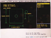
The Haas Visual Quick Code screen shown here shows a program for probing the center of a block.
During setups, Kennedy uses a conversational style of programming—Visual Quick Code—provided by Haas with its probing package. From a menu on the screen, Kennedy can choose from various probing operations, such as setting tools and locating fixtures or workpieces. Once an operation is selected, the operator enters information such as the work offset to be updated or the diameter of a hole to be probed. With these key values provided and the probe in relatively close proximity to the feature to be located, the operator pushes cycle start to initiate the operation.
VQC takes care of most operations required during setups and even handles probe calibration programming, which is required when a stylus is changed or after a machine crash. Calibration should also be done at least weekly.
Measuring Large Parts
Calibration and verification of the probe-and-machine combination to accurately measure machined components is vital to the probing system no matter how the probe is used: in setups, in-process or post-process. While it is more common to measure the workpiece off-machine, there are reasons for probing the part on-machine, in the fixture, after machining is completed.
For example, verifying that the machining process has performed as expected is important in many operations. This makes most sense on large parts, such as a weldment created by Dramco Tool and Die Co., Grand Island, Neb.
Because the flanged workpiece is more than 4 ' in length and 2 ' in diameter, it is too large for the shop’s conventional measuring equipment, such as calipers or micrometers.
Once the workpiece is machined on Dramco’s Haas EC1600 HMC, a Renishaw OMP40 spindle probe checks 16 dimensions and records them in macro variables in the machine’s control.
Dramco’s customer verifies every weldment, so the shop checks and records dimensions on each workpiece after it is machined and probed on the HMC. An inspection report can be prepared for each part and given to the customer for validation, an added value.
In most cases, it would be better to perform these checks on a coordinate measuring machine. The CMM can typically run the checks faster, freeing up machining time. However, large parts, such as the weldment, are difficult to maneuver into fixtures. With the part already in a fixture and the machining center having the capability to measure the workpiece, on-machine probing can save time compared with a process that would require refixturing on a CMM.
Periodic Calibration
One question that frequently surfaces about on-machine probing is if a machine tool can be trusted to measure true positioning of surfaces it machines using the same components used to move the spindle probe. The short answer is yes, provided the machine tool is properly qualified. The machine’s condition must be checked regularly to determine its ability to perform as expected.
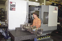
Todd Jacobson of Dramco with a weldment machined with dimensions checked in-process with an on-machine probe.
One way to assure a machine is capable of accurate measurements is to calibrate it. While the machine must be calibrated whenever styli are changed, such as when changing styli lengths or diameters or in case of styli breakage, the machine should also be calibrated periodically just to assure accuracy. The calibration process stores variables that provide a mathematical model of the location and diameter of the styli of both the tool probe and the spindle probe.
Gage tools of known dimensions (lengths and diameters) are used to set macro variables in the machine control to allow the macro programs to compensate for variations in probe locations and diameters.
Since probing systems use the machine axes to perform the measurements, thermal changes in the machine’s ballscrews will affect the accuracy of not only the machining but also a probe’s measuring capabilities.
Another way to qualify a machine is to place an artifact of known dimensions within the machine’s work envelope. If measurements of the artifact are inconsistent with the known dimensions, compensations for thermal growth can be made.
While some shops may be skeptical about the benefits of using probes on machine tools, others have integrated them into their daily operations. While on-machine probing does add some cycle time, many shops have found that benefits such as setup time reduction and on-machine parts verification can more than make up for this drawback. CTE
About the author: Dave Nelson is an application engineer for Productivity Inc. and a freelance technical writer. He works in the Omaha, Neb., office of the Minneapolis-based machine tool distributor. Contact him by e-mail at [email protected].
Contributors
Dramco Tool and Die Co.
(308) 382-5251
www.dramcotool.com
Rosene Machine Inc.
(800) 770-8854
www.rosenemachine.com
Royal Plastics Manufacturing Inc.
(308) 832-2760
www.rpm-composites.com
Related Glossary Terms
- calibration
calibration
Checking measuring instruments and devices against a master set to ensure that, over time, they have remained dimensionally stable and nominally accurate.
- computer numerical control ( CNC)
computer numerical control ( CNC)
Microprocessor-based controller dedicated to a machine tool that permits the creation or modification of parts. Programmed numerical control activates the machine’s servos and spindle drives and controls the various machining operations. See DNC, direct numerical control; NC, numerical control.
- fixture
fixture
Device, often made in-house, that holds a specific workpiece. See jig; modular fixturing.
- machining center
machining center
CNC machine tool capable of drilling, reaming, tapping, milling and boring. Normally comes with an automatic toolchanger. See automatic toolchanger.
- sawing machine ( saw)
sawing machine ( saw)
Machine designed to use a serrated-tooth blade to cut metal or other material. Comes in a wide variety of styles but takes one of four basic forms: hacksaw (a simple, rugged machine that uses a reciprocating motion to part metal or other material); cold or circular saw (powers a circular blade that cuts structural materials); bandsaw (runs an endless band; the two basic types are cutoff and contour band machines, which cut intricate contours and shapes); and abrasive cutoff saw (similar in appearance to the cold saw, but uses an abrasive disc that rotates at high speeds rather than a blade with serrated teeth).
- tolerance
tolerance
Minimum and maximum amount a workpiece dimension is allowed to vary from a set standard and still be acceptable.
- work envelope
work envelope
Cube, sphere, cylinder or other physical space within which the cutting tool is capable of reaching.
Author
News items authored by Cutting Tool Engineering have been written or edited by the editors of Cutting Tool Engineering magazine. The reports represent material submitted to CTE by outside authors, and edited by CTE editors for style and accuracy.