For a good part of my career, I thought of squareness—or, more correctly, perpendicularity—as a visual geometry. Many of the tools I use to inspect right angles are comparative and involve eyeballing, so it is natural to think of perpendicularity in visual terms.
Checking perpendicularity is a recurring theme on the shop floor—one that deserves detailed discussion and special tools.
The right angle is an invention of human mechanical arts. Its presence in nature is accidental and not by design. Perpendicularity is also foundational to the mechanical arts, so it is crucial to be able to measure perpendicularity with certainty.
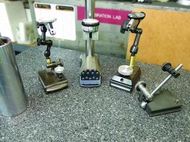
Figure 1. Tool and die makers have at their disposal simple, elegant tools for squaring parts to tight tolerances. Images courtesy of T. Lipton.
The closer the limits are that you need to work with, the more important it is to quantify the magnitude of the observed error. High-quality measurement feedback is necessary to produce first-class work. If you cannot verify your output, you never will be able to produce superior work.
So, you might wonder, “How square is that really nice machinist square I use to check my work?” The answer became obvious to me when I started to make parts and gages near the limits of my measuring abilities and found that some of my established references were not to be trusted.
The geometric dimensioning and tolerancing definition of perpendicularity is something like this: The surface must be perpendicular within X tolerance, with respect to the datum determined in the feature control frame. So, in reality, you need to know how far out of square a particular surface is to a specific dimension. Eyeballing is not good enough anymore.
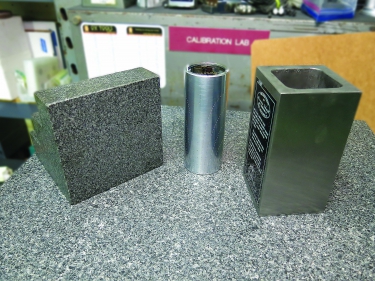
Figure 2. Normally, commercial and modified surface gages, which are sometimes called squareness comparators, are set using a master square reference, such as a cylindrical square, or a known calibrated right angle.
Faced with squaring parts to close limits, you must be able to rapidly determine how much to bias a part to bring it into tight-tolerance perpendicularity. How do we resolve this quickly and with certainty on the shop floor?
The good news is that clever tool and die makers have been doing it for years. Figure 1 shows some of their simple, elegant tools.
Normally, these commercial and modified surface gages, which are sometimes called squareness comparators, are set using a master square reference, such as a cylindrical square, or a known cali-brated right angle (Figure 2). A neat thing about this self-proving method is that users can establish their own perfect square reference, without access to any master right angle. By exploiting basic high school geometry, you can find dead-true square, as long as you have a basic, known, flat surface plate as a reference.
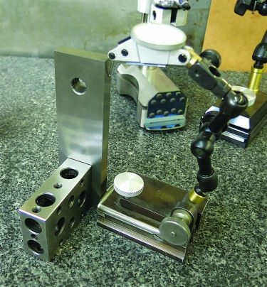
Figure 3. A common shop steel attached parallel to a 1-2-3 block as a demonstration piece for determining a true perpendicular reference.
The secret of these surface gages lies in the foot, or ball, projecting from the front near the base. The foot is rocked in a small arc when in contact with the part or calibration reference, and the high reading of the indicator sweep is the actual perpendicularity measurement. The instrument is typically set to zero on the right-angle reference, and part perpendicularity is plus or minus some dimension from the true-square zero point. The flat-faced model simply is butted against the part, reference or both, and the indicator is then zeroed.
Figure 3 shows a common shop steel attached parallel to a 1-2-3 block as a demonstration piece for determining a true perpendicular reference. The parallel is easy to verify accurately by sweeping the top surface relative to the surface plate with an indicator. Once it is confirmed as truly parallel, you can construct your right-angle reference. It makes no difference if it is actually perpendicular when you start, but the closer it is to eyeball square the better.
Using basic geometry, you can start with either of the two sides that were confirmed parallel. With the comparator, you zero the indicator on the first parallel side. Moving to the other parallel side, you take a reading and find that the second side reads +0.004" (+0.102mm). We know now that dead-true perpendicular is exactly half the difference of the two readings, or +0.002" (+0.051mm). If you zero the comparator at half the difference, you are now dead square. As proof, recheck the setup—your actual readings should show +0.002" and -0.002", respectively.
I have said it before, but it is worth saying again: A shop needs a high-quality, calibrated flat plane (surface plate) to do quality work. The flat plane is truly the foundation of the mechanical world—followed closely by the right angle.
Related Glossary Terms
- calibration
calibration
Checking measuring instruments and devices against a master set to ensure that, over time, they have remained dimensionally stable and nominally accurate.
- flat ( screw flat)
flat ( screw flat)
Flat surface machined into the shank of a cutting tool for enhanced holding of the tool.
- parallel
parallel
Strip or block of precision-ground stock used to elevate a workpiece, while keeping it parallel to the worktable, to prevent cutter/table contact.
- tolerance
tolerance
Minimum and maximum amount a workpiece dimension is allowed to vary from a set standard and still be acceptable.
Author

Tom Lipton is a career metalworker from the San Francisco Bay area who has worked at various job shops. For more information, visit his blog and YouTube video channel.