This column will show a timesaving setup procedure for milling keyways, flats or other features on shafts.
Shafts are a common component of industrial machinery. They are so prevalent that metal service centers keep round bar stock with close diametrical tolerances and polished surface finishes in a broad range of diameters and materials. This bar stock is known as “turned, ground and polished” or “drawn, ground and polished” for smaller
diameters. It accepts standard pulleys and gears and other off-the-shelf elements of machinery.
For power transmission purposes, all that may be required is to cut the bar to length and add keyways, flats or other features. I own a job shop that has been making shafts like this for 30 years. My shop has a customer that builds industrial machinery to order. I get a call when the client has a new machine to build or when replacement parts are needed for client machines in the field. Orders usually include a shaft or a few different ones.
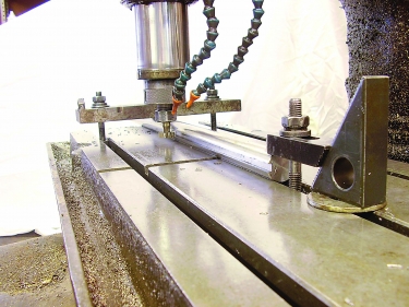
The right setup procedure can save time when milling keyways, flats or other features on shafts. Image courtesy of B. Taylor
When making a shaft of any material, setup time can become a big piece of the time-per-part pie. Over the years, I have come up with what I believe is the quickest way to get this work out the door.
In this example, I’ll show the fastest method that I know to put keyways in a shaft that is 31.75 mm (1.25") in diameter by 1,016 mm (40") long. The insight comes from understanding the machine tool that makes the part. (See the photograph.) Here, we are looking at a bed mill. The machine tool builder made the bed with T-slot grooves that have chamfered edges. The face of the bed, the width of the slots and the size of the chamfers are consistent from one end of the bed to the other. This allows a simple means to hold a piece of round bar parallel both horizontally and vertically to the x-axis of the machine.
Place the bar in the groove of a T-slot, and the chamfer sets the height of the bar from the face of the table. Then, all you need to do is clamp the bar in place. This table has three 15.875 mm (0.625") wide T-slots on 136.525 mm (5.375") centers. Two different clamps are shown in the photo. One uses conventional step block T-slot components. The other clamp is a piece of 25.4 mm × 76.2 mm (1"×3") steel bar with two holes drilled on 273.05 mm (10.75") centers. It accepts two T-slot studs placed in T-slots on both sides of the shaft being machined.
The cutter displayed is a woodruff keyway cutter used to cut the long keyway at a 90-degree position on the shaft. Endmills are used to cut keyways at zero degrees.
With this setup, the bar can slide along the T-slot groove, and the bed geometry ensures that the
centerline of the shaft stays parallel to the x-axis of the machine. This facilitates machining of shafts that are longer than the x-axis travel of the machine. Good visibility makes it easy to see that the radial positions of machined features are correct. I hope that this helps.
Related Glossary Terms
- centers
centers
Cone-shaped pins that support a workpiece by one or two ends during machining. The centers fit into holes drilled in the workpiece ends. Centers that turn with the workpiece are called “live” centers; those that do not are called “dead” centers.
- gang cutting ( milling)
gang cutting ( milling)
Machining with several cutters mounted on a single arbor, generally for simultaneous cutting.
- milling
milling
Machining operation in which metal or other material is removed by applying power to a rotating cutter. In vertical milling, the cutting tool is mounted vertically on the spindle. In horizontal milling, the cutting tool is mounted horizontally, either directly on the spindle or on an arbor. Horizontal milling is further broken down into conventional milling, where the cutter rotates opposite the direction of feed, or “up” into the workpiece; and climb milling, where the cutter rotates in the direction of feed, or “down” into the workpiece. Milling operations include plane or surface milling, endmilling, facemilling, angle milling, form milling and profiling.
- milling machine ( mill)
milling machine ( mill)
Runs endmills and arbor-mounted milling cutters. Features include a head with a spindle that drives the cutters; a column, knee and table that provide motion in the three Cartesian axes; and a base that supports the components and houses the cutting-fluid pump and reservoir. The work is mounted on the table and fed into the rotating cutter or endmill to accomplish the milling steps; vertical milling machines also feed endmills into the work by means of a spindle-mounted quill. Models range from small manual machines to big bed-type and duplex mills. All take one of three basic forms: vertical, horizontal or convertible horizontal/vertical. Vertical machines may be knee-type (the table is mounted on a knee that can be elevated) or bed-type (the table is securely supported and only moves horizontally). In general, horizontal machines are bigger and more powerful, while vertical machines are lighter but more versatile and easier to set up and operate.
- parallel
parallel
Strip or block of precision-ground stock used to elevate a workpiece, while keeping it parallel to the worktable, to prevent cutter/table contact.
Author

Brandt Taylor is owner of Berlin, Massachusetts-based Taylor Engineering, a machine shop.